Fast Tracks Turnouts

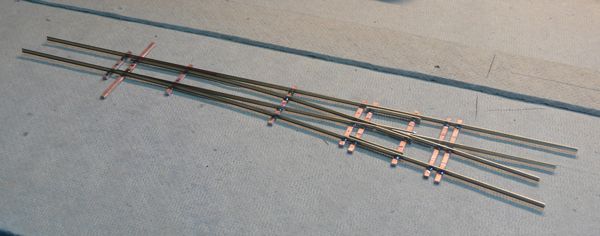
Well, here's the first attempt.

Needless to say, I was very pleased. This is a code 83, HO, number 6. I know Tim has better videos, but I couldn't resist giving it a whirl.
I'm new to soldering as well as to the hobby, so I think it's a testament to the Fast Tracks products, as well as their excellent videos and references that this turnout works as well as it does on my first try. For those interested, it took me about an hour and half to assemble this turnout.
The only problem I've run into so far is that the turnout ties I ordered from Fast Tracks are a bit thicker than the ones from Micro Engineering, and they don't match either the copper cross ties or the MEs. I know sanding will take care of that, but there it is.
I have a question for anyone who has or has made this (or Tim, if he notices this post). Is is a bad idea to use different rail sizes in the same switch?
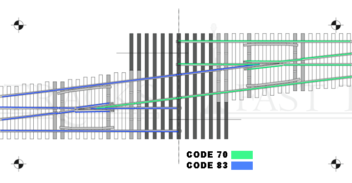
Let me explain. I'd like to make a single crossover, from the main (code 83) to a Siding (code 70). if i mix codes, especially at the frog point, will this cause performance issues, or am I better off starting the smaller rail after the turnout?
Here's an illustration to show what I mean about which code to go where.

>> Posts index
Navigation
Journals/Blogs
Recent Blog posts:
Comments
Its an illness....
That works so well you don't even need the track to get the wheels from one side to the other!
Looks great, and works even better. Is the crossover on 2" centres?
Thanks for posting the videos!
Cheers!
Tim Warris, Fast Tracks
http://www.fast-tracks.net
Follow us on Twitter for news, updates, special offers
and discounts only available in our tweets.
http://www.twitter.com/fasttracks
Scarpia, are you using a
Scarpia, are you using a regular #6 jig for two turnouts or are you using the fast traks crossover jig?
Chris
“If you carry your childhood with you, you never become older.” My modest progress Blog
2" centers, and 1 template
Tim, thanks - they are 2 inch centers.
Chris, I only have the single #6 jig - it took some experimentation to get this to work.
Because the diverging stock rail is also the opposite frog point, I measured and cut those first, which meant assembling the frog in total prior to soldering in the stock rail part. I also left off the ties past the frog point until very last, as naturally it didn't fit the jig with the ties from the other side of the cross over.
I did have to use a track gauge and solder the straight route stock rail and frog rail outside of the jig, but that wasn't too bad.
I have two more I'd like to make for the yard I'm working on; I may install the points and guard rails first, and attache the two frogs last on the next one instead of first as I did.
The nice thing is all parts are identical, so it wasn't too bad to make two sets of the identical switch parts. The biggest part was measuring the diverging stock rail / opposite frog section to where the tracks were centered properly. Now, though, I have a working model!
Flammable
I was in the garage with the usual suspects (in my previous layout in my previous house) when my nose flared... Sniff? Sniff? Sniff? Then the dread words were spoken, "Does anyone else smell smoke?"
Actually there were some others with twitching noses... Off went the layout power. Then came a detailed inspection of the the layout room by nostril. The smell seemed strongest over at the east end throat of Bear Creek yard. A scrutiny of that track work revealed that the cork under the points of one half of a crossover was seriously charred!
Further scrutiny revealed the cause of this conflagration in training - there was a foil whisker that had decided to move a thousandth of and inch or two and was shorting the track. Well not actually shorting, there was enough resistance in that pitiful contact patch that it wasn't drawing enough current to crowbar the digitrax booster (5 amps) - but it must have been pulling a couple of amps. Strangely the layout had continued to function even with this going on.
So what's the point of this dissertation? Two things:
I shudder to think what might have occured to the layout (and house) had this occurred while no one was in the layout area for an hour or two. 2 amps x 12 volts is 24 watts. Concentrated in small area 24 watts is more than enough to get really really hot. Since DCC always has full voltage on the tracks this is always a hazard.
Be safe, not sorry.
Charlie (smoky) Comstock
Superintendent of nearly everything
Fire safe
Charlie,
Great story and great advice! Killing power to the layout when it is not in use is a good idea, IMO.
My guess is the foil was acting like a load, only drawing enough power to heat things up without tripping the oveload protection and the DCC system just "saw" it as another loco drawing power. Overload protection is great in the case of a "DEAD" short, but in this instance you must have had a short with some impedance, an intermittent short, or a situation where arcing was causing heat but not tripping the circuit protection on the booster. All three of these scenarios can be a recipe for disaster if not discovered soon enough.
As you advise. Be safe, power down when the layout is not being attended.
I can hear it now ...
Yes, Charlie, I can hear it now ... (deep bellowing voice)
"Only YOU can prevent LAYOUT fires!"
Joe Fugate
Publisher, Model Railroad Hobbyist magazine
Read my blog
Fire Safety
I hope I didn't mislead you, Charlie. I simply had an old DC loco on a section of flex track wired to a DC powerpack. I attached the switch to the flex, and applied power. The loco would fail to move (due to a short), I would turn down the power, remove the switch, inspect/file, etc, and repeat. I did that until I found the offending thread of copper, than the loco ran fine, even over the switch.
I have all of my "layout" (I hate to use that word as it's really just a big test bed) power, lights, etc all on the same heavy duty extension cord. First thing I do when I go downstairs is plug it in, last thing I do when I leave is unplug it.
I still need to gap the frogs, and then power test the cross over, and while I need a better testing setup, for the moment this is working for me, and is pretty safe. I hope to do that tonight, and who knows, I may even have time to whip out another turnout!
Cheers!
It was the 'thread of copper'
It was the 'thread of copper' that got my attention having had the near fire situation on my previous layout due to a "thread of copper". Those threads are something that need attention - they should ALL be removed because even though they may not be shorting now, if bumped/disturbed by a finger or a piece of derailed equipment they spell trouble. The ones that are the real fire hazards aren't the ones where nothing runs due to a hard short - the trouble comes from a high impedance short (like the one I had). And with a DC power pack there's no power on the track unless you're there twisting the throttle knob. Its the combo of DCC and a near short - lotsa current but not enough to make the booster shut down due to its over current protection that are the danger. Just be clean with your PC ties (no hanging 'chads'/'threads') and it should be safe enough.
Sorry if I was confusing.
Charlie
Superintendent of nearly everything
Fast Tracks Turnouts
It is very simple to overlook, but carefully testing any trackwork that has soldered components for shorts is an important step in preventing these sorts of problems. Before installing any trackwork onto your layout, you should test for shorts using a multimeter. Or even better, a digital multimeter (DMM) as digital meters typically have higher and more sensitive resistance scales.
With your DMM set on the highest resistance scale available, you should have no conductivity between the rails whatsoever. I would even clip the leads from the DMM to the rails and flex the trackwork a bit to be absolutely sure there are no possible shorts. By testing each turnout or other piece of trackwork before you install it onto your layout, you are not only are ensuring that it is safe, but you will eliminate hours or even days of work trying to track down a short in a completed layout.
PC Board ties will sometimes have a bit of chaff on the edge of the tie that you need to be sure is removed. Pages 16 to 18 of our Builders Guide (http://www.handlaidtrack.com/documents/ug01.pdf) demonstrates the best way of preparing a PC Board tie to minimize the chance of shorts. Page 46 also details the importance of testing the turnout with a DMM for shorts after it is completed. I also demonstrate how PC Board ties should be prepared in our "Installing The PC Board Ties" turnout construction video here: www.tinyurl.com/dkr8js.
It is easy to overlook these small details, but they are critical to not only making the trackwork safe, but great looking as well.
Cheers!
Tim Warris, Fast Tracks
http://www.fast-tracks.net
Follow us on Twitter for news, updates, special offers
and discounts only available in our tweets.
http://www.twitter.com/
Well let me explain how stupid I really am
So it's my turn to explain how stupid I really am.
I was pretty darn careful with preparing the PC ties - I even checked them electrically after I gapped them before they went into the jig. I was certain the problem I found with the first one was that stray strand.
Nope. And the new crossover was failing almost all tests too (i dug my DMM out of the car tool box).
Thanks to Tim's post, I just went back and read through the instructions. I've read these before, and watched the videos a number of times - but still somehow forgot the to gap the switch point sides of the frog.
Duh!
Out comes the dremel, and voila, both the regular turnout and the crossover test perfectly. Who wudda thunk it?
Thanks Tim!
Unfortunatley the time I spent tonight on this precluded any more construction, and with 80 degree weather scheduled for this weekend, I may not spend too much time on more (although the thought of "mass" producing standard parts like guard rails and points on the patio is workable...)