Static Grass Applicator

(Please forgive the layout of this post, I have a hell of a time with this site getting images to simply align in the order I want. It may be a Firefox thing. You can find a more organized post here on my site).
I've been playing with scenery, and wanted to move my testing onto the static grass. The applicators seem the way to go, but I'd rather spend $200 with one of the advertisers here before buying a Noch version.
Thanks to this website that had a great break down of items to purchase, I got the parts, and started whipping my homemade version into shape.
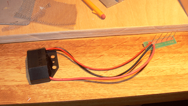
The key, it seems, is the negative ion generator. I know some folks have had luck with a electronic fly swatter, but in the middle of winter they're kind of hard to find, so I went ahead and ordered one of these. As an added bonus, it is 12 volt.
First up was a rough approximation of the tutorial.
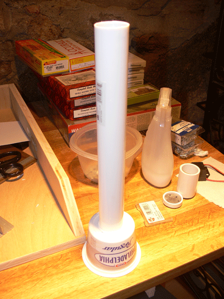
I realized after beginning construction that the shape isn't relevant to the function (or at least I believe). What is important is that the wiring is sound. The package is in some degree not material as long as the grass passes through the screen that is receiving the charge.
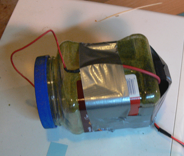
Based on that, and that I was having a hard time getting the two parts above to adhere, I went with a simpler model. It is smoked almond container, with the screen not glued in, but just pinned by the cap and the top of the jar. I liked the thicker plastic, and duct tape seemed to hold the electonics pretty securely.
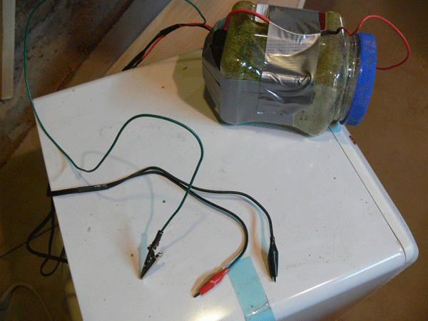
This ion generator is from the automotive world, and is 12 volt, which is the same voltage i realized as my MRC 12 volt powerpack. I have that powerpack on a toggle switch so I can go between DC and DCC on my layout; I figured why bother with another power source? The Red and Black alligator clips attach to any rail section, the green is for the ground. I just clip them on and fire up the powerpack to 80/90%.
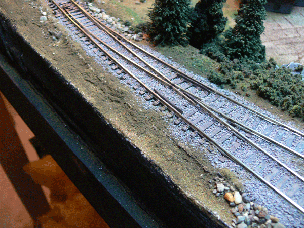
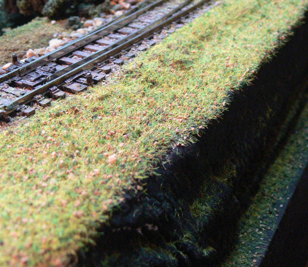
My question for this educated audience is the results. I am 98% sure the wiring is right as it makes a noise, and static electricity increases as the mesh gets close to the ground, but does the end result look right? As I haven't seen any in person, I'd like you to evaluate the before and after, just to confirm if I'm on the right track, or if I need to return to the drawing board. At the end, please find a before and after picture of the test area.
>> Posts index
Navigation
Journals/Blogs
Recent Blog posts:
BEMF
As an aside, decoders with a "Back EMF" feature compensate for the inductive counter force that a motor generates during rotation, varying with RPM. It effectively smooths changes in the motor's rotation by addressing load variation.
As another aside, Back EMF is what affects DC solenoid (relay) coil circuits; hence the inclusion of a properly oriented diode across the coil terminals to short-circuit the reverse voltage spike generated as the magnetic field of the coil collapses when the power to the relay is shut off.
The BEMF used by decoders has nothing to do with magnetic field collapse. DCC decoders use what is called pulse width modulation to control the power sent to an electric motor. At all times the motor is receiving either FULL power or NO power from the decoder. This makes it possible for the decoder to operate without a big heat sink.
Here's an illustration of what a 'high throttle setting looks like (voltage vs time)
_-----_-----_-----_-----_-----_-----
Notice the power is mostly 'on'.
Here's an illustration of what a middle throttle setting looks like (voltage vs time
___---___---___---___---___---___---
The power is on abouit the same as its offf
And a low power setting
_____-_____-_____-_____-_____-_____-
The power is 'on' only a little.
Some decoders let you program a 'frequency'. The frequency is the reciprocal of the time period over which the on/off division is made. The three (ascii art) wave forms each show 6 time periods. A lower frequency will result in the motor 'growling'. Decoders advertising 'silent' running will have a time period / frequency above what a human ear can hear (20khz / 50 micro seconds)
Now back to the BEMF feature. Given that a motor spins when power is applied to it (or at least it tries to spin) AND that a mechanical device has some momentum (and we go to extra lengths adding brass flywheels to add some momentum) - what happens for the portion of the time periods shown above when the motor is spinning but power is not applied?
The answer is a permanent magnet motor (like the ones in our models) becomes a generator! The voltage generated is (somewhat) proportional to the speed at which it is turning. A BEMF decoder knows when it is NOT driving the motor and measures the voltage at that time. From this it can deduce whether the motor is spinning faster or slower than it should (or at the right speed). If it's faster the decoder reduces the power sent to the motor. If it's slower the decoder increases the power sent to the motor. In effect this makes the motor / decoder combo into a servo. The amount of speed compensation may be adjusted (in some decoders) to make the BEMF speed control an 'assist' or make the motor speed lock to the throttle setting uphill or downhill, long train or short train. (I don't recommend this latter mode especially if running multiple units because minute speed differences between locos may result in the BEMF circuits fighting each other to establish THEIR speed as the correct one).
What about those diodes on relays? Well this is a completely different phenomena. When you have a coil of wire with current flowing through it a magnetic field is developed around that coil. This is true for electromagnets, the windings of an electric motor, or the winding of a relay, or an automotive ignition coil.
What happens when power is abrutly removed from that coil? The answer is the magnetic field 'collapses'. A generator works by moving a wire relative to a magnetic field causing an induced current. If a wire is stationary but a magnetic field is moved past the wire (or coil) it generates an induced current. When the magnetic field around a relay coil collapses when power is removed it generates (or tries to generate) a lot of current. If there is a high impedence (resistance) path outside the relay (such as having the power switch for the relay opened) then the voltage generated as a result of the coils attempt to create current can be very high. In the case of an automotive ignition coil this effect can generate thousands of volts (although those coils are specially designed to do this).
Even a standard relay winding can generate a LOT of voltage. Enough to 'arc' over those switch contacts causing pitting and eventual switch failure in a switch used to control a relay. If the relay is driven by solid state electronics the high voltage can fry output transistors.
But putting the diode around the relay winding the current generated by the collapsing field is shunted through a relatively low resistance path and the voltage never builds to a dangerous level. The control switches or transistors driving the relay are saved.
A decoder has to deal with this also as each time the power is shut off to the motor (and its windings) there is a field collapse and a voltage spike is generated. The BEMF circuitry needs to absorb these spikes without frying and ignore them when measuring the BEMF.
BEMF motor speed control will NOT work on a motor driven by pure DC as there is no opportunity to put the motor into 'generator' mode to see how fast it is spinning.
Whew... that got a bit long for which I apologize.
Cheers,
Charlie
_ _ _ _ _
Superintendent of nearly everything
Back EMF
Charlie said:
"Whew... that got a bit long for which I apologize."
Not at all Charlie! I found the parts pertaining to decoders very interesting and the rest was a good refresher for me. An enjoyable read all around.
clarification
"The BEMF used by decoders has nothing to do with magnetic field collapse."
I did not say that it was related to field collapse in this instance. However, Back EMF generation is caused by the same principle in both cases. It does not matter if a magnetic field moves across a conductor or a conductor moves through a magnetic field. The result is identical.
What I said was "decoders with a 'Back EMF' feature compensate for the inductive counter force that a motor generates during rotation, varying with RPM. It effectively smooths changes in the motor's rotation by addressing load variation." I avoided a full-on dive into PWM control as I had only jumped into the thread to correct the electron flow comment. The first Back EMF note was an effort to link the voltage/EMF concept to a term that modellers would likely have seen mentioned in DCC literature, but might not know what it related to. The second Back EMF note was to provide, and hopefully explain, another model-related situation that people may have heard about which used the same term.
The free (unpowered) rotation of the motor between pulses causes the motor windings to cut through the fixed magnetic field of the permanent magnets, inducing a current which the decoder measures as a 'counter electromotive force' to the applied voltage. Should a motor encounter a situation that increases its load (up grade, entering curve, mechanism bind) or decreases its load (down grade, returning to tangent from a sharp curve), the BEMF decoder will automatically compensate for these load variations over subsequent pulse durations to ensure that the motor (and locomotive) doesn't speed up, slow down, or stutter in an undesired manner.
As the relay coil is turned off, the collapsing magnetic field cuts (incredibly) rapidly across the windings of the relay coil, thus inducing a (relatively) large momentary current in the windings. This 'counter electromotive force' is of the opposite polarity to the previously applied voltage; thus the need for the 'reverse bias' diode to short-circuit the BEMF induced spike and protect the relay's driver circuit.
Visit the S Scale Workshop blog
Bit of an update
So I got some longer and different static grass, and dismounted the ion generator. Here are the results.
Grass update
Scarpia,
It looks like you are having fun with your static grass applicator. The new grass in that area looks good. It's hard to tell from the pictures how irregular the grass is.
One of the tips I picked up from the scenery DVD's... while the glue is still wet use a flat blade screwdriver or similar tool to knock down a few random areas so they appear matted or trod upon. It makes the grass field look a bit more natural.
Looking forward to seeing what else you are up to.
Tweaks
I've seen that "pressing some grass flat"; I don't know how necessary it is in this application.
I have a couple of other tweaks I need to try, one is to wet the grass (just dampen), due to the dryness in my basement. The second one is a bigger screen for the longer (6mm) static grass.
My idea of using the device as a snap on to any package has failed in sorts. Things I hadn't considered -
what I am doing is simply holding the ion generator in one hand while I shake with the other. I will mount it to a shaker, I don't think using the stock containier is going to work in all applications.
Tweaks
Scarpia,
Yes. like I said it's hard to tell from pictures what the finished product looks like with your own eyes. It's only necessary if you are not happy with the look of the field.
I'm not sure I understand your reasons for wanting to dampen the grass? Is that after it is laid or before? The air in our house is really dry during the winter months. What issues are you having that you hope to alleviate by dampening? Just trying to learn from your experiences. :o)
The Noch applicator comes with two screen caps, a fine screen for short grass and a coarse screen for the longer grasses. I wasn't aware of that before you mentioned it. Now I know that when I go to build an applicator I'll have to look at building two end caps with different screens in them. Thanks!
I agree the applicator can't be full. You have to be able to shake the contents.
Thanks for sharing your trial and error experiences. I'll have that much less to try and err at when I do it.
Dampen
I got the static grass from Scenic Express; in the box they had a large paper catalog that had an article on how to use the Noch applicator. It mentioned in there that it works better with humditiy, and in a dry environment, to dampen the grass in a bowl (just mist with a sprayer) before spreading.
I'll give it a whirl this week and let you know.
A couple of more pictures
I have to say, that I am pleased with the results of this.
Here are a couple of more pictures.
Pleased
Scarpia,
I should say. The scene looks great!
Did you try the dampening technique at all yet?