Second step and finished ...
... maybe.
A first test run on a test track showed that the tender power pickup was not an absolute safe solution. Maybe because I have not used the connecting cables to engine for lights and so the keep-alive unit did not work? Maybe because the rails were not clean enough or maybe that the tender did not have enough weight for a permanent all-wheel contact on rails?
My decision was that I have to add the power pick-ups on loco and additional eight wheels should solve this problem. However the problem was that I could not remove the wheel sets from frame! But no, it was not a solution to me, to add pick-up wires under the bottom plate of frame like spider legs!
My idea was to install contact bolts inside of frame which are sliding on inner side of insulated wheel rims. The second pole is given by the mass of frame and so there were enough space for pick-up contacts inside of frame. However, the contact bolts must go through one wall of frame, well insulated!
However there was a lucky solution!
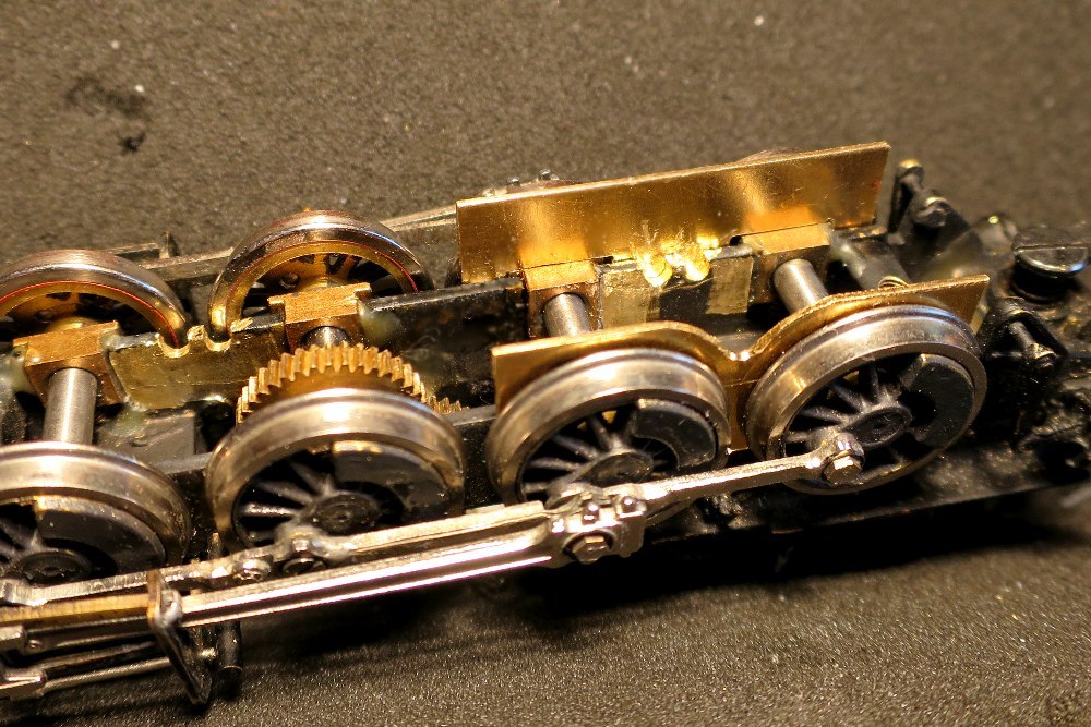
Some times ago I received a few new high-speed milling cutter from a dental laboratory and so I could mill four cut-outs in one frame side - using small brass sheets for protecting the wheels, which I have set on axle bearings between frame and wheels. This picture shows a first step of these cut-outs, at end they must be enlarged a lot.

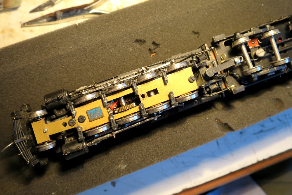
This picture shows one of the brass contact bolts guided in short steel tubes which are glued into styrene blocks which I can fix with small screws on connection sheets of frame. The contact bolts are pressed by soft flat springs against the wheel rims (not visible here) and the longer tube ends are secured by black insulating sleeves against short circuit with frame. And last, the red cable is prepared for the connecting to decoder.
With this solution and together with the milled cut-outs I could build all parts of power pick-up on my worktable. That all would have been much more complicated if I had had to build everything part by part inside of frame.
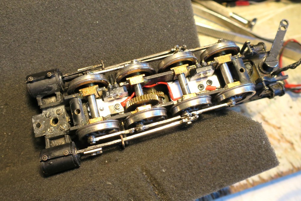
This is the frame with mounted pick-up contacts which slide on insulated wheel rims now. (The red cable does not touch the large tooth wheel or second axle, there is enough space between. This is only the bad perspective of photo which gives this impression of touching parts.)
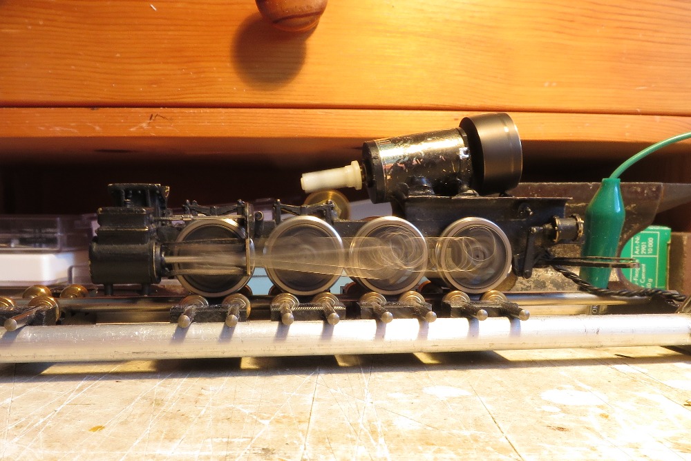
After completing the model this all looks so ...
A new running test showed very good results now, without spider legs, however with an eight wheel power pick-up on each rail and also without the capacitors of keep-alive unit! You see the absence of second cable connection from tender to engine yet and so there are no power to leds on loco or from/to capacitors. All in all I was very lucky with this result!
And this is an interesting side effect for solving problems with motor, gear or all other problems at loco.
Such an equipped brass model can run now also without its tender by this complete power pick-up ont all wheels at the loco.
A short addition too.
Today I received two long wished pictures of G1 from N&W Historical Society which I have added to my gallery now. One of it should be of a special interest - a drawing (blue print) of class G, the predecessor of G1. However there are no big differences between these both classes and so you can find a very close drawing of this engine.
For viewing open my gallery please, because I received permission for using these pictures on my website only. Sorry!