marcoperforar


So, is a helix with a 2% grade and a 30" radius equal to a grade of 3.1% on the straight?   The magnitude of curved track on pulling power is larger than I have sensed.

Fred W.  wrote:

"The equivalent grade for curved track came from John Allen.  I have never found any evidence beyond it being Allen's hypothesis for a formula for the extra drag created by curved track.  It would have some basis on Allen's experience in HO scale using trucks before the days of RP25 wheels and free-rolling wheel sets.  A practical experiment (pure speculation on my part as to Allen's conduct of any supporting experiments) would be to check how many cars a given locomotive can pull up a known straight grade as can compared to how many cars can be pulled around a known radius curve.

"As a photographer, John Allen would likely have been familiar with 1/x type formulae.  If his data points gave him a curve that resembled the chart, it would have natural to fit a c/r curve to the data, where c is a constant and r is the radius.  Remember that Allen would not have had computers to optimally fit curves to the data.

"And Allen's formula makes sense if one assumes flat treads.  With a flat tread, there is a differential in path distance around any curve for the two wheels.  This causes wheel slip (hence increased friction), with the friction going up at a non-linear rate as the curve gets sharper.

"Most RP25 treads use the maximum allowable 3 degree taper for ease in manufacturing.  The taper means that the wheel set can adjust to curved track without wheel slippage until a certain minimum radius is reached.  What that radius is depends on how far into the flange root you will allow the wheel to move to compensate for the unequal path lengths.  When I ran the calculations, I found you typically you moved into wheel slip around a 20" radius in HO.  Exact track gauge, wheel gauge, and how much use of the flange root you allow all affect the final value a couple of percent.

"Bottom line:  my theory is that with modern tapered wheel sets and decent flange root radius, there is very little extra friction on curves until around the 20-26" radius point (in HO).  At that point there would be almost a knee in the curve, with significant increases in friction for radii less than the knee.  Again, I have no proof of my theory, nor have I conducted any experiments to prove/disprove it."

Fred W

Design of Railway Location by Clemen C. Williams published in 1924 says this, in part, about this subject.

"Where curves occur on the ruling gradient, or on grades nearly equal to the ruling gradient, the rate of grade must be reduced in order to permit the locomotive to pull its train with no more resistance than it encounters on a tangent on the same grade..."

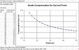
The book cites American Railway Engineering Association rules which call for compensating curves by between .03 and .05 percent for each degree of curve.  Several factors, including the relationship of the train and curve length affect the choice of compensating factor.

Adjusting degree of curve to HO-scale radius, an 18-inch HO-curve is equal to a 45-degree prototype degree curve and a 33-inch curve is equal to a 24-degree curve.  So, an 18-inch curve should be compensated by reducing the grade by from 1.35% to 2.25%, and a 33-inch curve should be compensated by reducing the grade by from 0.72% and 1.2%.

Oddly to me, John Allen's adjustment factors of 2% and 0.95% for these two curvatures are comfortably within the range of the early twentieth-century AREA rules.

Nevertheless, I think these factors for HO are something like twice what is necessary.  This subject would be a great magazine article for an author who had facilities where the effect of curvature on train resistance could be tested on models.


Mark Pierce

Reply 0
mikeruby

Compensation of curves & grades

In practice I've found that where I have an almost constant  4% grade on a 30" curve, which then leads on to a very slightly steeper straight my trains will generally stall on the straight track, as the track is almost straight lower than the curve, the same amount of train is in the curve. Most of my trains are fully on the grade before they stall, and some shorter trains are coming off the curve when they stall e.g. passenger. It could be the curvature combined with the angle of the trucks give greater traction.

That passenger train has more locos on order!

Mike Ruby

Reply 0
marcoperforar

where to locate the maximum compensation

I suspect the worse problem for us modelers is when the locomotive first comes off the curve since it loses the extra friction for its powered wheels from the curve while the train is creating maximum resistance....This suggests that the maximum amount of grade compensation for curves should be along the upper end of the curve and a distance of straight track beyond.

Mark Pierce

Reply 0
Cuyama

varying compensation might be recipe for disaster

Seems like it would be a real challenge to successfully fine-tune the compensation to that degree with the typcial model railroad construction methods, particularly for helixes with trains of varying lengths, with and without helpers, etc.

Seems the better approach would be to lessen grades generally through curves,

Reply 0
marcoperforar

My second disagreement with Byron

Quote:

Seems the better approach would be to lessen grades generally through curves,

That's the whole idea.  My last post suggested that the uphill end of the curve and some distance above it on the straight should be lessened a bit more than the rest of the curve.  I don't see a disaster coming from there.

The question is: to what degree grades need to be reduced to compensate for curves so the effective ruling grade is consistent.  For example, we don't want a consistent grade of 3 percent which allows for a 20-car train on straight track but stalling on a curve where only a 16-car train can negotiate.  Better to have the grade increased on the straight and reduced on the curve so an 18-car train can make the hill.

Regardless, any calculation won't be perfect unless every train is the same.  For instance, longer trains will encounter more resistance on a curve than a shorter train within the curve.

Hopefully, someone could do some experiments so we might have a better idea of how much the compensation should be.

Mark Pierce

Reply 0
bear creek

I got bad news for you

It will depend on WHICH 18 cars you have in the train. The types of trucks, the brand of wheelsets (especially plastic vs metal treads and plastic vs metal axles), the type of track, how dirty the wheels on the cars are, how dirty the wheels on the locos are, how dirty/pitted is the track, do you use any kind of oil on the track, etc. Oh yeah, and are those 18 cars all 40', 50', 34', 85', etc. etc. etc.

You'll likely find that formulai will not be much help in pin pointing the exact amount of grade that's possible on a curve without the train negotiating the curve stalling. If you're building with 3% grades and curves expect that you're likely going to need a bit of extra loco power up front. If you're building a helix with 3% grades and tight radii (30" or less in HO) expect that you'll need considerably more power to go up that helix than to go up a straight grade.

Only experience will tell you how many locos of which types are needed to get a most obstinate of your trains up your grades. Plan on it. Add helpers if needed. If helpers aren't feasible then reduce train length.

Dealing with grades is part of the charm of having grades on an operating model railroad.

Cheers,

Charlie

Superintendent of nearly everything  ayco_hdr.jpg 

Reply 0
marcoperforar

Yeah, that's the real world for you

Yes Charlie, there are so many variables which cannot be predicted.  Yet, the prototype tried to address them, and I'm not about to throw my hands up and not attempt to make some kind of compensation.  Perhaps the best solution is to use "C" clamps on one's risers and operate for an extended time and adjust the grades minutely until one achieves the best compromise.  Is that a plan, or not?

Mark Pierce

Reply 0
bear creek

It's your railroad so by all

It's your railroad so by all means do what you think best. I did it the other way around. I built it and then measured how many "average" cars each loco could pull up the grade. I made "loco-motion" cards for each loco giving that number. When the crews are in the yard at the bottom of the hill they check whether they've enough power - if not they yell for a helper.

One other thing the protype has going for them - if they're off and inch or two of elevation in 100' feet it is just about negligible. If we have a roadbed that is 1/16" too high or low over a distance of a 1'3" (about 100' in HO) then that becomes a LOT more significant.

Cheers,

Charlie

Superintendent of nearly everything  ayco_hdr.jpg 

Reply 0
marcoperforar

Real-life railway engineers designed rairoads for efficiency

Charlie, you obviously weren't trained as an accountant as I was (CA license 27272).  Real-life railway engineers designed rairoads for efficiency within available financial resources, and in that way have lots in common with accountants.  When I see a locomotive's drivers spinning at one particular spot on a grade, limiting the amount of train than can make the route, I wonder how I might have tweaked the grades a bit so there is no trouble spot unnecessarily limiting train length. 

Regardless, we all have fun in our particular ways.  Keep those early Alcos' long-hoods forward!

Mark Pierce

Reply 0
marcoperforar

Don Mitchell once wrote...does Joe Fugate have more info?

Don Mitchell once wrote "See table 11-3 in my Walkaround Model RR Track Plans book which delineates John's [John Allen's] research. For those unable to get the book (it's out of print), use the formula: Compensation Factor = 32 divided by Radius in inches. (Note: the formula printed in the book inverted the 32 and R.). The CF= 32/R formula is pretty accurate. For example, when Joe Fugate reworked the helix in his layout, the calculated values per above turned out to be within a tenth of a percent or so of what he found in practice before and after."
 

Perhaps when Joe has time to spare, he might share his experience.

Mark Pierce

Reply 0
marcoperforar

Don Mitchell's comments

I received the following message from track planner Don Mitchell today.

First, the formula was based on empirical data obtained by John Allen and his operating friends.  Thus, it is an approximation rather than a true mathematical equation.

Second, almost all properly constructed curved grades have vertical easements at top and bottom.  These will help compensate for any change related to curve friction.  Note that all curves that are changing to tangents have to do so before the curve reaches 360 degrees.  Otherwise,  a helix results and the grade most always has to continue to provide clearance between levels.

Third, the formula was intended as a planning guide rather than as a determination of actual train performance.  I can't recall a layout, either one operated on or one created when I was doing custom layout design, where any difference was operational significant.

At most, the difference was the mentioned tenth of a percent or so on Fugate's layout or the adjustment of a car or so in train length.  The common practice is to actually run an engine on the constructed grade to determine how many cars it will pull.  The grade adjustments I'm most aware of have been to smooth out the grade rather than to change its percent.

Fourth, the entire train has to be on the curved grade for the formula to be applicable.  The helix case as been mentioned, but it should also be valid for a series of "S" curves that is long enough.

Finally, if you know what an engine will pull on a grade of, say 2%, then the formula will give you a close approximation for planning what the corresponding grade has to be on a given radius for that engine to pull the same number of cars.  If engine performance ratings on tangent track are not known, then it is plan, construct, and finally measure actual performance.

If the measuring is done on the most severe grade before the rest of the layout is constructed, then -- perhaps -- it would be possible to make grade adjustments throughout.

There is also the Fugate case.  Had Joe applied the formula to his first helix, he would have been able to determine a radius for a helix with a lesser grade that gave performance more in line with the other grades on his layout.

As an aside, there has been some discussion on line about deriving a more precise formula or formulas.  Given what I've seen in 65 or so years of HO modeling, it's my  opinion that such a project would not be worth the effort.

Don M.

Mark Pierce

Reply 0
marcoperforar

train versus curve length

Quote:

Fourth, the entire train has to be on the curved grade for the formula to be applicable.  The helix case as been mentioned, but it should also be valid for a series of "S" curves that is long enough.

So, if the typical train is longer than the curve or curves it occupies, the John Allen's compensating factors should be reduced.  Of course, helixes are almost always longer than any trains, so helixes need the maximum necessary compensation.

Mark Pierce

Reply 0
mikeruby

Working out grades

 When I was designing my layout I first did some trials. I weighed a 40' car and then made up a short train and placed it on a grade that my plan had determined, knocked up from bits of timber. I then ran sets of locos to see what they could pull by adding known weights in the cars. From this I could tell if my locos could pull enough cars up the grade before I started (I know I didn't have enough wheel set friction on the short train, but it did work). I also found Athearn SD70s are weedy compared to Kato. This was a bit rough but the results closely match what now happens on the layout. 

I now have rules for how many cars per loco are allowed in a train, depending on direction (different grades east and west) it works well.

Mike Ruby

Reply 0
bear creek

Are you saying you tested

Are you saying you tested your locos pulling power on a grade by using a single car to which you added different amounts of weight?

Charlie

Superintendent of nearly everything  ayco_hdr.jpg 

Reply 0
mikeruby

Test train

I think I used about six coal gondolas in the train, and then weights including food cans, placed in the cars to make up the train weights.

Mike

Reply 0
bear creek

I'm not sure that 6 cars

I'm not sure that 6 cars weighted to be like 20 would exhibit the same amount of drag on a long curve. You're results may be off a bit.

Charlie

Superintendent of nearly everything  ayco_hdr.jpg 

Reply 0
mikeruby

Test train

I agree that in theory they are not equivalent, but it did work. It could be partly because the drag of the grade is massive compared to the drag from the curvature.

Plus at the time I did it the plan was not finished, I was trying to find out what was possible. Lastly temporarily laying out the grade on a curve would have been difficult.

Mike

Reply 0
mikeruby

Open loads

 After all my experiments into the loading of my trains, I forgot one thing. As I run a lot of lumber cars I have now started adding loads to the flat cars, along with gondolas and hoppers. The added weight has now taken the train weight above what 2 locos can haul for my maximum length local train (has to fit in the shortest passing loop).

Looks like it is back to helper service, which I had original planned, but then dropped to give slightly longer trains. At least this means longer running times for west bounds as they take on and drop off a helper.

I already have a quick formula for working out the number of cars in a train depending on car length. I now need one for if a helper is required depending on the number of loaded cars in a train. Back to experimenting!

Mike Ruby

Reply 0
proto87stores

drag depends on total angle turned, not radius per se.

A very good summary of the problem and practical situation, of curve wheel slip, including a correct assessment John Allen's empirical results. My only concern would be that you are relying heavily on the root radius climbing up the rail to justify not slipping on the 20" or so radius you mentioned. If you just have the coning, the slipping theoretically starts at a much larger radius. Around 6 ft  if I remember correctly

I went through some of the math when Joe Fugate was evaluating his helix a coupla years back. What i found was that the extra distance the slipping half of the wheel set traveled depended on the angle it was turned through, rather than the radius of the curve. Just like the old riddle about tying a piece of string around the Equator and then adding an extra piece. The radius increase is still the extra length divided by 2Pi. The radius of the globe can be 2" or 2 trillion miles. The radius increase stays the same

This goes a long way to explaining the rather different results some people experience.  The slip work for a set number of cars simultaneosuly turning through an angle stays the same. The rate at which that work is done, depending on how fast the angle is being turned, which of course, at a constant speed,  involves the radius.

In practice, apart from just dropping all curved grades by 30-50% below your straight line equivalent, you need to keep either as few cars on the curve at a time as possible or turn the longer trains by a lesser angle. Basically this means widen the radius as much as possible on any helix. A small radius helix is a double whammy because the turn rate is greater, the grade is greater and a longer train may well be going round more than 360 degrees if the small helix is multi-layer.

To a lesser extent, you also have to watch out for even flat dogbones, loops and zig-zag curves. All of those will add a lot of drag, especially if they are as long as your long trains. 

HTH

Andy Reichert

Andy

Reply 0
ChrisNH

So an Oval?

Andy.. if I understand what you are explaining, an oval with a tighter radius may be better then a larger radius circle for a helix?

Chris

“If you carry your childhood with you, you never become older.”           My modest progress Blog

Reply 0
proto87stores

non-standard helix curves

Chris,

That's a very good question!

I wouldn't know an exact answer without plotting the exact track diagram. Clearly there is no free lunch in Physics, so I doubt there are any magic bullets in this area. And I'm sorry to say the maths would be too complicated for me without working out a more general formula first. I'm not that proficient on the subject that I could just trot out a quick right answer. But I suspect you could have some quite different results depending on the ratio of curves to straight, and train length.

One interesting possibility, if you had the space, would be to have stretched out ovals that only have grades on the straights and keep the curves flat. That way you wouldn't get both problems at once. It would be a heck of a lot easier to construct too!

But I think the real solution is to keep all grades low and all curves wide regardless. Whatever shape you come up with, all the cars in the train will cumulatively end up turning the same total angle eventually.

Andy

Andy

Reply 0
BDF

Oval Helices

Just my personal opinion, the shape and size of the helix is not only dependant of the location and available space on the layout, but also the restrictions of the layout in one particular dimension. For example, if you had a room 16 x 10’ room. In N scale you could do an around the walls with a peninsula in the middle. Placing the helix at the end of the peninsula instead of a turn back would enable a double deck for more mainline, staging or whatever. 

In this case it’d be beneficial to lengthen the helix with straight sections to reproduce the same actual grade rather than going for a larger radius. Ex. An 18” radius with 12” straight sections, with a 2” climb per turn (tight but doable) is a grade of 1.45%. A radius of 22” would be required to have the same nominal grade. That extra 4” can eat up valuable isle space in this small of a room but the loss of one foot in length of mainline is fairly inconsequential IMO. It’d be very interesting to see a comparison of effective grade vis-à-vis a larger radius.

 
Reply 0
tunnelmotor2000

Davis fomula

Seems to me that some research concerning the Davis formula applied to model railroads is needed.

However, I think to have a working formula, all cars should have the same weight regardless of their lenght.

On the other hand, maybe we are pushing it too far. There was a time that we were told that if your train stalled on a grade, you simply added an engine or removed one or more cars.

Reply 0
joef

Regardless of the precise formula ...

Regardless of the precise formula, the truth still holds - when the entire train is on a curve, there is more drag than when the train is on straight track. Don't move to a real small radius curve on a helix to save space - you'll be sorry.

In fact, one clever trick to save space would be to use a tight radius but make the helix into an oval, with at least two car-lengths of straight track between the curves. This will give drag relief and should work well to deal with this issue yet allow a tighter radius to save some space.

If you can, it behoves you to build some test track and check train peformance before you commit to a given helix design if the helix radius is going to be less than say, 3.5x your longest rolling stock length. If the helix will only be 1-2 tiers, it may not be as important either.

But if you're planning a fairly tight radius helix (under 3.5x of your longest rolling stock) and you want it to have 3 or more tiers, you should do some empirical testing to validate that it will work as you expect, because the extra drag issues may cause problems.

Joe Fugate​
Publisher, Model Railroad Hobbyist magazine

[siskiyouBtn]

Read my blog

Reply 0
shoggoth43

Diesel Spotters Guide v2

There was an older version of the Contemporary Diesel Spotter's Guide ( the blue one ) that had some interesting formulae in it.  One was the % vs. degree compensation typically used on the read deal.  I have no idea what it is now but .5% per degree curvature seems to be stuck in my head.


-

S

Reply 0
Reply