Ken Hatch kenwhatch

hwork(2).JPG 

I am examining the use of foam board in benchwork. This module is nominally 24” x 72” x 5” with a 72” center span and 24” cross members on 18” centers.

The boards are 2 x 3/16” laminated with Gorilla Wood glue (because that’s what I have).

Top will be 3 x 3/16” foam board.

Equipment is Bachmann On30.

The main question: is there data to show what foam board’s structural needs are or is it empirical (i.e. found a combination that didn’t collapse)?

Ken

Imagining the SP&S in N and HO in the late '60s...

Freelancing the Portland & Yamhill Railway narrow gauge (55n3) in the early 1940's. Roughly based on the Oregon Electric’s proposed McMinnville extension.

Here's my blog Index

Reply 0
Ken Hatch kenwhatch

Using interlocking notches

etail(1).JPG 

The sides are laminated with an additional 6” x 5” piece to support the cross members.

20middle.JPG 

Top view of center span and cross member. Cross members have 6” x 5” pieces on either side. Just because, I guess.

20detail.JPG 

No joints have been glued yet. This assembly is to confirm location of center span’s notches prior to cutting. As it turned out, one notch location was off by 3/16”. Whew!

Ken

Imagining the SP&S in N and HO in the late '60s...

Freelancing the Portland & Yamhill Railway narrow gauge (55n3) in the early 1940's. Roughly based on the Oregon Electric’s proposed McMinnville extension.

Here's my blog Index

Reply 0
Ken Hatch kenwhatch

Full plan

x12%20v4.jpg 

This module would part of a 4 ft by 12 ft layout (with extension for wye.) Current plan is to use part of a two car garage. Modular sections for ease of transport to and from Room of Requirement (Music/Library/RR Work Room). Support for benchwork modules is TBD.

The rest of the house is fully (over-) populated with furnishings and wall decor. At 65, I’m tired of playing trains on the floor.

I’m not an engineer nor have I ever played one on TV.

Again, the main question: how do I know if this is structurally sound? Trial and Error or Math(s)?

Thanks for any input.

Ken

Imagining the SP&S in N and HO in the late '60s...

Freelancing the Portland & Yamhill Railway narrow gauge (55n3) in the early 1940's. Roughly based on the Oregon Electric’s proposed McMinnville extension.

Here's my blog Index

Reply 0
railandsail

Foamboard Type?

What type of foamboard are you using? There are many types, and some not so durable.
 

Perhaps have a look here,..  https://model-railroad-hobbyist.com/node/30281?page=1


I would strongly recommend this 'cellular PVC'  foamboard,..... Strong, lightweight, totally water-proof, easily cut with any woodworking tools, strong gluing using std cheap PVC cements that plastic pipe guys use.


Reply 0
Prof_Klyzlr

Response

Dear Ken,

Thoughts and responses in order of appearance:

Firstly, looks like a nice use of 5mm Foamcore

Quote:

I am examining the use of foam board in benchwork. This module is nominally 24” x 72” x 5” with a 72” center span and 24” cross members on 18” centers.

Interesting dimensional choices. Previous discussions here on MRH, esp RE "TOMA" suggested that 6' (72") long is pushing the limits for single-person movement. Multiplying that by 2' (24") wide makes for about the largest single-piece element one would want to try and move around single-handed.

Example : typical domestic single-person 30" external doorway thru laundry
(as say, one might need to navigate while moving a module from garage or shed --> inside house)

nch_door.jpg 

Example : domestic single-person 42" internal hallway with dogleg, "train room" at end

ain_room.jpg 

That said, given your overall 12 x 4 "island" footprint mission, I "get" why you've chosen those dimensions.

The 18" spacing of the cross-braces is a bit farther-apart than I would instinctively use, but not by much. For reference, my default and go-to spacing is 16" under (typically) 4' proscenium modules.

Example 1:10 4 x 2 x 2 Proscenium  with 16" "profile/mid-bracing" spacing.
(Click on the "Example" text to download a PDF of the design.
Print with NO SCALING, glue onto cereal box cardboard,
cut out the elements and assemble...   ).

088256_n.jpg 

4 x 1 "foamcore plank", 2" thick, reccomended mid-bracing 12-16" spacing.

rside_01.jpg 

5" is an interesting depth measurement. Are you intending to have any "below track earthworks" like trestles, creeks, etc? If Yes, you may want to (re)consider the depth measurement, and seriously pre-engineer the locations of the earthworks and related structural-mods to accomodate.

curvy_01.jpg 

d_layers.jpg 
 

3-14_468.jpg 

are_LEDs.jpg 

Green_02.jpg 

green_04.jpg 

_Room_01.jpg oorong11.jpg 

Quote:

The boards are 2 x 3/16” laminated with Gorilla Wood glue (because that’s what I have).

I personally use straight White (PVA) Glue for laminating foamcore, but by-all-means you gotta use what you got on-hand...

The keys, whichever glue you use, are:
- Glue and weight on a flat-surface
(UNLESS you are deliberately creating a "pre-tensioned" foamcore element)

- Skreed the glue thin and consistent accross the entire surface, you are wanting a full-surface-bond.

Quick sidenote, I think I see overlaps in the long-side members. Is this because your starting with sheets that are < 72" long? Laminating for strength (doubling the thickness of the side members) is arguably redundant,
(more on this later), but laminating "to allow overlap/extension using shorter-sheet-parts" makes sense...

Quote:

Top will be 3 x 3/16” foam board.

Should work fine, will easily handle up-to 4 kilo/9 pound Brass O2R Challengers, so On30 equipment
(B'mann Stearns Heisler is approx 500Grams/1 pound) should be handled easily. It must be said that we are NOT building a platform which needs to benchpress an F-150 pickup truck!

nch_copy.jpg rside_01.jpg 2x laminated Foamcore thickness "deck" handles an Atlas O2R MP15 (1.2Kilos) + Overland Brass CA11 Caboose (0.7Kilos) with ease...

Foamcore.jpg 

Quote:

Using interlocking notches

... is highly reccomended! "Tab-in-slot" works great in Foamcore, and is a great match with either White (PVA) Glue or Low-Temp ("craft" type) hotglue.

Tab-Slot connection between Profile "C" and rear structural member

-slot_01.jpg 

Cross-brace tab/slot "T-joint" with front lower-fascia

-slot_01.jpg 

However, the Over-Riding Rule is:

- Never, and I mean NEVER cut, chop, notch, or thin a Foamcore element such that it is Less Than 2"!

2" seems to be the point where Foamcore simply does not have enough "meat" to be useful, and this becomes particularly critical when considering the "spine" part of a "C-shaped profile" of a proscenium module. 

Note how the mid-backdrop stiffener in the pic below is Vertical, as opposed to Horizontal. This is because the spines are only 2", and if that mid-backdrop stiffener was tab/slot-ed, it would reduce the spine to (only) 1", which is not enough to withstand the "spring force" of the matteboard coved-backdrop sheet...

r3qtr_01.jpg 

Part of the reason why I'm harping on this is that you've noted your module is (only) 5" thick. By "half/half tab-in-slot-ing" the Ends and Mid-module Braces with the longitudinal centreline member, you have reduced those members to disturbingly-close to the "minimum 2" dimension"...

...it will still work, just be aware of the material performance envelope...

Speaking of "tab-in-slot", how are you creating your "tabs" and "slots"? Your example pics look great, so you've obviously got tools and techniques sorted...

"Homebrew" dbl-bladed knife, 3mm aluminium means a perfect 5mm (3/16") slot, every time...

l-bladed.jpg 

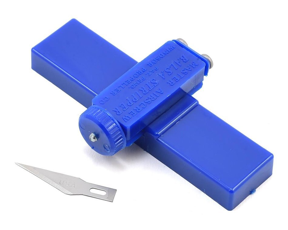
Master Airscrew Balsa Stripper - IMHO essential for consistent easy "edge trim" and "tab"/"dovetail" creation

Quote:

Again, the main question: how do I know if this is structurally sound? Trial and Error or Math(s)?

Honestly, engineering in Foamcore is equal parts "Art and Science". There is not-so-much the kind of "X mass over Y Span = zero deflection" material-performance-specs available for Foamcore as for other more "hardware-y" materials. I mean, it's not the first time Model RRers have pressed a "normally used for" material into a service it was never tested or intended-for!  

This is also compounded by the use of Monocoque and similar structural designs, which counter-intuitively produce stronger/more-rigid structural assemblies than their constituent materials would suggest is possible. (aircraft wings from paper-thin sheet aluminium, etc),
but are much-harder to "calculate manually in One's own brain"...
(It's not a straight-forward "X times Y = Z" equation,
pass the Atomic Weights + Theodolite + Finite Material Non-Destructive Analysis rig...   ).

However, many decades of experience in Australia, the UK, and even the US provides a wealth of evidence that, engineered and assembled properly (as you very-much appear to be doing, or at least heading-towards   ),
combined with a firm honest assessment of the actual loading and use-case-stresses the modules will face,
suggest that Foamcore should be well-capable of achieving what you're asking...

I hope this helps. For further reference, reccomend checking out:

https://model-railroad-hobbyist.com/node/19222

https://model-railroad-hobbyist.com/node/18802

https://model-railroad-hobbyist.com/node/19638

https://model-railroad-hobbyist.com/node/19903

https://model-railroad-hobbyist.com/node/27299

https://model-railroad-hobbyist.com/node/42363

Happy Modelling,
Aim to Improve,
Prof Klyzlr

Reply 0
Prof_Klyzlr

Questions arising

Dear Ken,

Questions arising from your provided pics and descriptions:
(In no particular order of preference)

- I see a curved trestle on your trackplan at Bottom Right of the 12 x 4 island.

How deep is the "under-track earthworks" intended to be?
Have you accounted for this in the structure of the relevant module?
One end of the trestle appears to end awfully close to the module<> module joint?

- What support system/structure do you intend to use with these modules?

- How are you considering achieving/maintaining physical alignment the modules?

- How are you considering handling the cross-module track-joints?

Happy Modelling,
Aim to Improve,
Prof Klyzlr

Reply 0
MikeHughes

Re tab in slot …

I personally can’t see the point of weakening the foam-core “joists” by cutting slots in them when a butt joint with a fillet of hot glue on each side for the joining piece would be just as strong, and a lot less work.

You wouldn’t tab and slot wood or steel, so why foam-core, which has even less strength to start with?

If the slot is deemed desirable for a vertical load on  a cross brace, then why not completely glue a double layer of’ say 4” wide laminated foam-core plate with a slot in it where the joists will mate.  Short of like a foam-core “joist hanger”.  This is what Ken_Watch appears to be doing.

With the expanded room a available to my B&H, I am going to extend the layout using foam-core double deck modules.  I haven't yet decided whether to make them free-standing, or sit them on top of Ikea drawers (I need the storage) that match my workbench.  I’m also imagineering a foam-core helix with an inside vertical spline and in er and outer columns for support.

Reply 0
MikeHughes

Foam-Core Helix?

Anyone aware if this has ever been done?  

I’m looking for a source of paper and plastic coated (“waterproof”) foam-core 2’ x 4’ sheets in the Vancouver area.  I could go as large as 4’x 8’, but its harder to transport and store at this size.

It’s amazing how many places show up in Google searches for this stuff, but none of them outside of art and office supply places actually carry it outside of 24” x 36” or smaller sizes.  And the list of variants is endless.  Foam Core, Foam-Cor, Fome-Cor, etc.  I see some that even comes with heat activated and also peel and stick adhesive on one side.  Always paper coated it seems though, which would likely be better for glue.  

Reply 0
Prof_Klyzlr

Tab in Slot

Dear Mike,

Quote:

I personally can’t see the point of weakening the foam-core “joists” by cutting slots in them when a butt joint with a fillet of hot glue on each side for the joining piece would be just as strong, and a lot less work.

I'll give you that it would be "a lot less work",
(money being no-object, I'd love to have a 60" x 40" laser cutter,
would make cutting out foamcore components with all tabs/slots RTR   ),

but a "DoveTail" or "Tab-in-Slot" foamcore joint does absolutely give a stronger and more reliable joint than a "butt joint". Indeed, I've temporarily-assembled complete 4x2x2 foamcore proscenium modules for clinics, and swung them over my head, using nowt but masking tape to hold the base and rood fascia corners together. This was only possible because all other joints were tab/slot connected, and thus were mechanically solid, sans glue.

The key is to not cut thru more than half the width of each member,
(whether using "halving" X-joints between centreline member and cross-braces,
or a "tab-in-slot" T-joints between braces and fascias),

and the remaining continuous material on each member Must Not be less than 2".
(Got over 2 decades of Foamcore layouts worth of experience, on which this is based).

Quote:

You wouldn’t tab and slot wood or steel

Um, please see "Mortise and Tenon", "Rabet", and "DoveTail" joints, all used extensively in wood assemblies...

ALL such joints are used in in preference over surface<> surface "butt joints" for inherrently better joint strength,
(mechanical interaction beats simple "surface<> surface friction"),

make for "fall together correctly" alignment of assemblies,
(IE ensuring alignment, and orientation of layout module pieces),

and a key technique for "monocoque" and pre-tensioned assemblies...
(think aircraft wings,
proscenium modules with coved backdrop/roof members,
or modules with curved fascias, examples posted earlier and elsewhere on MRH).

Happy Modelling,
Aim to Improve,
Prof Klyzlr

Reply 0
ctxmf74

72" by 24" ?

Have you looked into hollow core closet doors? They would be a bit longer than 72"  but are ready to go and pretty light. One could stack foam sheet or glue risers on top of the door to create terrain...DaveB

Reply 0
Prof_Klyzlr

FoamCore Helix and Vancouver sources

Dear Mike,

Don't have access to my main machine right now, but seem to recall MR doing an article on building a helix using "Mi-Core" (a tradename variant of foamcore) back in the 90s? 

Marshall Stull also documented some foamcore helix work on his Blog from back in 2013
http://smallmr.com/wordpress/a-helix-in-foam-core/

and given suitable engineering, I've yet to find a plywood-based layout-structure that I couldn't successfully adapt to foamcore, so the common "plywood-based" helix designs
(curved roadbed + plywood strip "risers") could well be fair-game...

FWIW, "Foam-Cor" is the original and official tradename of the 3A Composites product.
"foamcore" is a generic name, covering most other knockoffs
"Kappaboard" is a common alternative name in the UK and Europe.

For official 3A Composites Foam-Cor in/near Vancouver, try:
(in no particular order of preference)

- PolymerShapes : Pitt Meadows BC
https://www.polymershapes.com/locations/vancouver/
/> https://www.polymershapes.com/product/foamboard-and-paperboard/

- EM Plastics : Delta BC
https://www.emplastic.com/catalogs/cp_/product-catalog/substrates/foam-boards

- Laird Plastics : Langley BC
https://lairdplastics.com/catalogs/cp_/shop-by-material/foam-boards

- Uline : Burnaby BC
https://www.uline.com/BL_870/Uline-Foam-Core-Board?keywords=Foamcor

All look to supply 60x40 x 3/16 (my personal choice for all MRR Foamcore tasks),
and some have 4x8 and larger sheets...

Happy Modelling,
Aim to Improve,
Prof Klyzlr

PS just took a (re)look at the Helix kits by Trackside Scenery,
again a laser cutter would make things a lot faster/easier (draw once, cut many),
but I can see some interesting correlations...

Reply 0
ctxmf74

  "I personally can’t see

Quote:

"I personally can’t see the point of weakening the foam-core “joists” by cutting slots in them when a butt joint with a fillet of hot glue on each side for the joining piece would be just as strong, and a lot less work."

Building light weight wooden boats I've made butt joints by filleting the corner with a filler compound then taping the bulkhead or frame to the hull with glass and resin. For a foam core layout that doesn't need to be water proof the fillets could be fixall and the tape could just be cloth or some kind of paper applied with white glue. ....DaveB

Reply 0
Ken Hatch kenwhatch

Further comments

Brian: Thanks for link. This build is a Proof of Concept and Request for Comments. As such I’m using Dollar Tree foam board. I’ll spring for the better stuff later.

Prof_Klyzlr: Good info as always. I have had a few threads open in the browser for reference. I’ll check the new ones.

As for design decisions, I’m using 20”x30” sheets, hence the laminating. Why 5” deep? 20/5=4. So 4x30” boards from one sheet…

Which then resulted in “how many sheets do I need without too much waste?”

tingPlan.jpg 

Since we/I are using empirical data, I thought that over-engineering would be safe.

From /node/37235?page=3

…Foamcore is equally applicable to building "domino" modules.
The below simple "domino" has 12" between braces and 2" deep sidemembers/girder-webs…increasing the depth of the sidemembers would increase the rigidity and raw load-rating of the assembly, …

Serendipitously, a 2.5” notch leaves 2.5” of foam board, which is “OK” per your standard.

teCutter.jpg 

Because I rarely throw anything away, I remembered my 40+ year old X-acto matte board knife. That, t-squares and a regular x-acto handle did the work.

Answers to follow-up questions:

Trestle is at open end of module. Depth is TBD. I will puzzle that out once I get this module done. Some of your pictures above may give guidance.

Module support will probably consist of 1x3 wood legs and tops. Still in “not yet fully formed” stage.

Thinking of 1/8” ply plates inside and out of sides mating with same on other modules. Then bolts and nuts. Also under development.

Same with track joints. There are a number of solutions to be found. I am trying to avoid too much planning at this point. Sometimes I work better if I have the pieces in hand. Else, nothing gets done.

odolite.jpeg 

…pass the Atomic Weights + Theodolite + Finite Material Non-Destructive Analysis rig... 

Not sure about the FMN-DA rig (same source as flux capacitor?), but I’m good with the theodolite (in taller box below). Belonged to my great-grandfather (white tie) whose first job with his civil engineering degree was with the Northern Pacific in North Dakota and Wyoming.

BootGang.jpg 

Ken

Imagining the SP&S in N and HO in the late '60s...

Freelancing the Portland & Yamhill Railway narrow gauge (55n3) in the early 1940's. Roughly based on the Oregon Electric’s proposed McMinnville extension.

Here's my blog Index

Reply 0
ctxmf74

"but I’m good with the theodolite"

They were still using those old type when I first started surveying. Later we'd sometimes take one with us when retracing old surveys due to their compass matching the old work better. Most surveyors called them transits or more likely the gun, office guys might call them theodolite :> ) ....DaveB

Reply 0
Prof_Klyzlr

The plan...

Dear Ken,

Quote:

As for design decisions, I’m using 20”x30” sheets, hence the laminating. Why 5” deep? 20/5=4. So 4x30” boards from one sheet…

Which then resulted in “how many sheets do I need without too much waste?”

I hear you, and it makes complete sense. I too have (too) many WORD DOC outlines of 60 x 40 Foamcore sheets, with various combinations of component layouts to try and maximise material usage. Curved modules tend to be the most "wasteful", (as curves often are), 
but I always seem to use up even the most oddball-shaped offcut pieces...

Indeed, a side-project in the works at the moment has had me furiously planning foamcore cutting-templates,
so your design-thoughts struck a particularly relevant chord...

Quote:

Since we/I are using empirical data, I thought that over-engineering would be safe.

I hear you. One of my ongoing challenges is nailing the lines between:
- "Home layout" (pure foamcore, supported by existing/seperate structure)
- "Light Touring" (the occasional show/exhibition/meet, Foamcore "hardened" with carpet or enhanced fascia)
- "Heavy Touring" (full-on Qubelok ladder-frame with Foamcore proscenium, completely self-supporting)

and the fine-details in design and construction that optimise the balances/compromises for each application. Building "Heavy Touring" versions is relatively easy, (Engage "Over-engineer for safety" mode),
while still out-performing common wood and metal constructions in weight, ease-of-transport and handling, cost, and sheer "liveability",

but finding the tipping-points for the other-end of the spectrum, that's where I'm finding the really-interesting engineering and thought-exercises lie...

Quote:

Because I rarely throw anything away, I remembered my 40+ year old X-acto matte board knife. That, t-squares and a regular x-acto handle did the work.

Agreed. One of the things I do like about foamcore construction is that it is literally just "a ruler, an X-acto knife. and a hotglue gun". The "dbl-bladed knife" and Master Airscrew stripping tool are single-digit $ "toolbox upgrades", but they are far-from-mandatory, and such "minimal tool requirements" brings this benchwork technique into the realms of any modeller...
(no power-tools, or related skills required, zero noise, and virtually zero mess).

Quote:

Thinking of 1/8” ply plates inside and out of sides mating with same on other modules. Then bolts and nuts. Also under development.

On my latest builds, I have used 3mm MDF as the "mating surface plates",

ofile_01.jpg  Build_01.jpg 

Quote:

Same with track joints. There are a number of solutions to be found.

Indeed. I would reccomend checking out the recent work by Tom Conboy,
specifically his "Wetterall Food Services" and "Herrin Micro" layouts...

Quote:

I am trying to avoid too much planning at this point. Sometimes I work better if I have the pieces in hand.

Makes sense. Foamcore is an interesting material though, While it takes "on-the-fly" adaptions and changes well, (EG on my last build, I spontaneously carved away over 2/3rds of the front edge of the foamcore base fascia to accomodate a river...),

it's use with "engineered structures" and monocoque assemblies means that major structural challenges
(such as trying to fit a 4 1/2" deep trestle on a 5" deep domino module), really would benefit from some focussed pre-planning...

Looking forward to seeing how your foamcore On30 adventure develops...

Happy Modelling,
Aim to Improve,
Prof Klyzlr

Reply 0
Ken Hatch kenwhatch

Transit vs Theodolite

DaveB,

A couple of years ago I was researching this instrument. As far as I can tell, it is more correctly a transit than a theodolite. The difference between the two is beyond my ken so I use the terms interchangeably.

Not sure how it works, though. Tried looking through it. Perhaps the focus was set quite distant.

We always enjoyed watching the engineering students at Oregon State locate the corners of buildings... "Hey, buddy. It's right where it's always been!"


Ken

Imagining the SP&S in N and HO in the late '60s...

Freelancing the Portland & Yamhill Railway narrow gauge (55n3) in the early 1940's. Roughly based on the Oregon Electric’s proposed McMinnville extension.

Here's my blog Index

Reply 0
ctxmf74

  "As far as I can tell, it

Quote:

"As far as I can tell, it is more correctly a transit than a theodolite. The difference between the two is beyond my ken so I use the terms interchangeably."

Hi Ken, From what I recall the first theodolites had longer scopes so could not be inverted( turn the scope end to end) when they changed to shorter scopes they called them transits because rotating the scope end to end was referred to as transiting. Your instrument should have a nice scope on it, you can test it by focusing on a distant object ( should be at one end of the focus range) When you look at closer objects the field of focus will be pretty short. If you can't see anything when you look thru the scope check to see if it has some kind of lens cap on it. The main focus ring should be on the scope near the eye piece, and a smaller focus for the cross hairs should be somewhere nearby. These old guns were pretty rugged so I'd be surprised if it still didn't work. You will need a set of legs for it ,and it needs to be leveled for the compass to work. ....DaveB

Reply 0
MikeHughes

Thanks Professor, I get it now

It appears that ken is basically using the “Housing Joint” shown in your diagram of joints.  I had the idea you were joining boards egg-crate style.  Your approach preserves the total strength of the main beam, and looking more closely at Ken’s photos, it appears to be what he is doing as well.  

Much appreciate the links to the helixes and Vancouver suppliers as no one I could find locally has anything longer than 3/16” thick and 36” long.  I want to build 4’ modules more or less like these ones I did at home with 1x4 and 1/4” plywood.

F5ABF9C.jpeg 

Reply 0
Ken Hatch kenwhatch

Using house terms

Mike Hughes,

If we call the long boards beams and the short boards joists, then yes I’m using a plate (incorrectly called a cleat in my diagram) as a joist hanger. So the beams have one ply uncut, one ply with notch and the notched plate.

Because I tend to get over-eager, I glued the center beam to the joists only to later discover I forgot to cut the tabs on the beam ends. After cutting them (unsupported, and with a dull blade) I realized I had the tabs on the bottom, not the top.< sigh>

To compound my problem, I had cut the notches in the end pieces through both layers, then added the plate. < double sigh>

Test fitting showed the end pieces were almost, but not quite, cut to correct length. < shrug>

Fortunately, cutting replacement end pieces won’t be a problem, nor an expense. I might even learn from the experience!

Ken

Imagining the SP&S in N and HO in the late '60s...

Freelancing the Portland & Yamhill Railway narrow gauge (55n3) in the early 1940's. Roughly based on the Oregon Electric’s proposed McMinnville extension.

Here's my blog Index

Reply 1
Prof_Klyzlr

Dbl-stacked Prosceniums

Dear Mike,

Out of interest, what are the Height and Depth dimensions of your proposed 4' long "dbl-stacked" proscenium modules? (Length is set at 4', confirmed...   ).

Happy Modelling,
Aim to Improve,
Prof Klyzlr

Reply 0
railandsail

foamcore helix

@ MikeHughes

This example is gatorboard,...

But I think pvc foamcore is cheaper and as strong if not stronger.

I used it to built my structure for my long viaduct/bridge,...and I used it to build a new pit for my diamond scale turntable.

Reply 0
MikeHughes

Professor … The Dimensions …

My Double-deck modules are 18” deep x 48” long x 381/2” tall outside dimensions.  

The upper deck is about around 18” above the lower if I remember right.  I’m not home at the farm to measure.

Not sure when I will get home to fetch the plane, as the nature of the noise suggests the engine in my Rubicon has a failed connecting rod bearing.  

Reply 0
MikeHughes

Thanks Brian!

That Helix video is great. Gives me all sorts of ideas.

Reply 0
anteaum2666

Foam Helix

I did not build a foam core helix, but I have built three foam helixes using 5/8" extruded foam.  You can read some details about that on my blog below, if you are interested. All have worked flawlessly (to my amazement!)

https://model-railroad-hobbyist.com/node/24931?page=1


Michael - Superintendent and Chief Engineer
ndACLogo.jpg
View My Blogs

Reply 0
Prof_Klyzlr

Dbl-stacked Proscenium - redux

Dear Mike,

The pic of your dbl-stacked plywood proscenium

F5ABF9C.jpeg 

has been haunting my mind the last day or so, I'm sure I'd seen something similar somewhere previously...

...oh, hold-up, that's right...

_Modules.jpg 

ba dum ching!

...but seriously, I've been rolling your stated dimensions around in-head and on-paper, and I foresee some interesting "maximising sheet usage" schenannigans in your future. Indeed, using my personal preferred 60" x 40" sheets, I keep returning to the idea of forming the "dbl stack" from 2x "standard" prosceniums. With strategic sizing of top and bottom sections (1200mm VS 1190mm + laminated overlays), they could be engineered to literally "slot on-top of each other", while still being 100% self-supporting. By sectioning the "E" profile into 2x interleaved "C" profiles, (and maybe tweaking some key dimensions a touch), it may also be possible to get all required components from three 60x40 sheets...
(+ a pair of matteboard sheets to form the coved backdrop/roof surfaces)

Can't wait to see how the project develops...

Happy Modelling,
Aim to Improve,
Prof Klyzlr

EDIT: just had another swing at it, and with the following dimensions:
- Overall Module Height : 37"
- Overall Module Depth : 18"
- Rear Spine Depth : 4" (scene depth therefore = 14")
- Lower Deck/Mid Deck/Roof height/thickness : Nominally 3" ("coved sky" sections may be angled)
- (Scene height for each level : 14")
a 60x40 sheet can provide 4x "E" profiles, IE enough for a 4' module,
with a still-useful 40 x 16 sheet of material to spare...

Reply 1
Reply