Scarpia

As I approach the next construction, I am interested in using materials that would limit as much as possible material travel due to changes in humidity. At my domicile stabilizing the humiidity level is simply not fiscally feasable, so I am wondering if there is another way to deal with the issue.

I would seem that changes to trackwork that are forced through expansion and contraction of the substructure can be negated if the substructure itself doesn't expand or contract. In order to do that, it must therefore not absorb or shed water. After some consideration, I've developed some concepts based on the followiing requirments.

  1. Must be able to support a multi-level layout.
  2. Must be strong
  3. Must be allow minimal, if any humidty absorbtion.
  4. Must be cost effective
  5. Must be durable
  6. Must  be "mountable"
  7. Entire units need to be free standing capable (I don't want it to be put against a wall.

Framework Substructure - Engineered Metal Studs

Engineered Metal Studs come in a variety of sizes ( Widths: 1-5/8 In., 2-1/2 In. and 3-5/8 In. Manufactured in 8 Ft., 10 Ft. lengths), and cost approximately a little more than twice that of wood (Approx. $4.75 per piece).

Pros

  • Strong
  • Durable
  • Re-usable
  • Not affected by humidity
  • Light weight.

Cons

  • Price
  • Conductivity.

Metal  stud based construction is assembled with basic tools and screwed together in a similar method as traditional wood (a different saw blade is required).  Knockouts are already in place for wire conduits.  Appearance can be improved with paint or other treatments. Conductivity can be negated through proper wiring insulation practices. Price may be offset by other advantages, and may not be as relavent in the overall scheme of the construction (e.g. framework substructure costs with metal equals 8% of total layout construction cost as opposed to 4% wood materials)
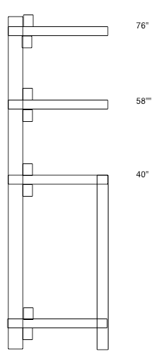
Substructures assembled into standing units of three ribs on a 24" interval. completing a unit of 4 feet in total over all length.. Each rib consists of a single vertical piece in the back, four horizontal pieces to support from top to bottom valance, layout level, layout level, and storage. Each Rib to be connected to the others in its unit with longitudinal cross pieces that support the horitzontal pieces.

Every other longitudinal cross piece can be staggered to join with other units when in place. Additional longitudinal cross pieces of other materials (such as wood) may be attached to the front of each horitzonatal piece to support fascia and other non-vital systems.

The Road Bed Laminate.

The next consideration is what the track itself will sit on. Based on some of the same criteria

  1. Must be strong
  2. Must be allow minimal, if any humidty absorbtion.
  3. Must be cost effective
  4. Must be durable
  5. Must  be "mountable"

I am looking at a combining a couple of common materials into a homemade laminate. The laminate may consist of

1/4 inch homosote (under roadbed and structures only)
1 inch closed cell foam
1/4 MDF

large panels can be created for areas such as towns or yards,  or strips for singular road bed. The laminate should be flexible to a degree, but strong enough to support the required weight. The underlying MDF allows for switch machine mounting, wire management, and sound deadening. Each laminate to be created by applying adhesive and pressure. By only using homosote under areas such as the road bed and structures, the top of the foam maybe carved for small depressions and ditches.

Thoughts?


HO, early transition erahttp://www.garbo.org/MRRlocal time PST
On30, circa 1900  


Reply 0
Scarpia

Road Bed Laminates

So with that ouline in mind, I'd like to open this up for criticism. Fire at will!


HO, early transition erahttp://www.garbo.org/MRRlocal time PST
On30, circa 1900  


Reply 0
BlueHillsCPR

I like the masonite spline

I like the masonite spline like Charlie used on his Bear Creek layout.  Joe uses a similar method in his DVD's.

Reply 0
peter-f

I'll not comment on the wall

I'll not comment on the wall supports- that's site-specific. But the 40" level has a leg AT THE FORWARD EDGE of the framing.

I'd move it back toward the wall 4 to 8 inches (cantelever the 40" layout  shelf Over the leg and the 6-8" storage shelf around it) because (no matter how diligent you are or intend to get) you Will Kick the leg and the resulting 'layout-quake' will frustrate you to no end!

In my case, the layout is attached to the wall, extends out 18 to 48 inches (it's a C shape- widths vary) and the legs are 6 to 18 inches from the front edges.  I still knock them a bit... but I'm usually Under the benchwork when I do that... and no trains run (road rules!) while service is performed.

If you build a foam laminate... look into foamcor (1/2" thick) it comes in small sizes at art supply places- but is manufactured in 30x40" sheets.  Custom photo-finishing shops may direct you to a local source.  I use it for landscaping - not roadbed.

Steel stud may be sourced from commercial DEMOLITION shops- see if a retailer is moving out near you!

Hope this helps.

-Peter

- regards

Peter

Reply 0
Scarpia

Thaks Peter

Thanks for your suggetions, Peter. These are meant to be a free standing unit - I think I need them to be at least 24" deep for stabilty as they are going to be supporting the weight of an upper level and valances.

What isn't shown here, because I need to go look at the available materials, are the joists that are going to run across the top of this. With those and the fascia, there should be a minimum 3-4 inches of overhang (up to 12 inches for deeper sections). I'm hoping that will be enough.

The joists are not shown as I'm not sure yet on the material. I need to go look and see what's available, in a non-wood form. The steel structures, being C shaped, negate the need for L-Girders as you can tie a joist into the top of each C, but I'd like to use no more than a 2 inch high joist. If I can't find economical steel materials for the joists at the right size, Than I'll have to use lumber, which means it can still move under changes in humidity which sort of negates the whole idea. Sure, a mixture of steel and lumber will move less, and if I used ripped 1/2 inch plywood for joists and risers that may be acceptable, but I'd really like to get minimal movement if possible.

I should have time to go and look carefully at Home Depot at the end of the week; by then I'll have a better idea. I may still make one unit this weekend, at worst if it doesn't work out as benchwork, it should make a decent workbench and storage unit.


HO, early transition erahttp://www.garbo.org/MRRlocal time PST
On30, circa 1900  


Reply 0
Scarpia

Pricing addendum

I just ran some quick numbers -

Using 3 5/8 inch steel studs, (approx. a 2x4) the cost per 2x4 foot unit is $51.96. That price is for 10.5 pieces of 8', plus 2 8' pieces of 2 1/2 for joists.

Using 2 1/2 inch steel studs for the structure as well as the joists, the price per 2x4 foot unit drops to $46.50.

A wooden structure, using 2x4 construction, would run half the cost - $20.37.

For the layout as I've designed it at this stage, 10x14, the total benchwork cost (8 units total) in metal would be $415, as opposed to under $200 for lumber.

The question stands -  are the advantages of a steel substructure worth the cost.


HO, early transition erahttp://www.garbo.org/MRRlocal time PST
On30, circa 1900  


Reply 0
peter-f

Look into furniture

Look into furniture hardware--

Now I can't think of who carried it (Loews?) or even it's name- but I've used connectors that have keyhole shaped openings to capture screwheads- (used on bedframes?)  They come to mind because -as a free-standing unit, your uprights will need bracing against 'racking'- that non-square near upright condition that will weaken your product.  his hardware is simple and strong- and breaks down easily, too!

[for reference: my framing is 1x3+1x3 (solid) glued legs and beams, 1x3+1x2 girders.... attached to the wall, its very sturdy- though I didn't build it to be walked on.  humidity in NJ hasn't(!) been a factor (yet- only 3 year history to report)- but I sealed the wood with shellac before adding any trackwork.]  IMO - wood will be fine.

Best of luck!

- regards

Peter

Reply 1
Scarpia

Benchwork Revision

After running the numbers on the cost of an all metal structure, I went back to the drawing board. Re-evaluating the use of wood, I took a hard look at it's biggest drawback for my purposes, the contraction and expansion. I remembered, however, that the movement only occurs in two axis - the length of a piece of wood doesn't change, only it's width.

With that in mind, I wondered if it would be possible to use a metal support structure that can "ride" on a wooden subset. Interestingly, my first attempt at planning it kinda resembles rails on ties.  By mounting metal studs on the tops of wooden posts, there is no vertical movement; and by making the drilled hole in the metal 1/8" larger than the lag bolt used to mount it and by only hand tightening, the metal L girder assembly (girder and risers) should be able to float back and forth if needed, keeping the railroad above it in a stable situation relative to itself.

I cannot think of a way currently to support the upper level and valance without using a metal stud; my thought here on assembly is to fix the vertical stud tight to the L girder assembly, but again using the same method outlined above, only "loosely" attaching it into the lower part of the wooden legs (mostly to keep it in alignment.) Naturally the risers of the L girder assembly can be extended out well past the basic unit dimensions.

These are designed as 2x4 foot units that would be connected by pieces not shown. For the top, I think connecting multiple pieces would provide the lateral stability needed, but additional bracing might be required.

Here they are. Thoughts?

 /></p><p><img rel=


HO, early transition erahttp://www.garbo.org/MRRlocal time PST
On30, circa 1900  


Reply 0
Scarpia

1:1 Model

today I got the parts needed to assemble one unit. Naturally things immediately had to change, as I couldn't get 2x2's and I just decided to go with the 2x4s instead.

I cut each leg to 37" length, and these 1x3 strapping pieces to 24".  Each end set was assembled first.

 /></p><p>and when done, if all is good and square, they should be able to stand on their own.</p><p><img rel=

next up I layed it face down on the floor, and began attaching the rear 1x3 strapping (48" long). I have these clamping squares from Rockler, they are great for holding things into shape while you assemble.

 /></p>


HO, early transition erahttp://www.garbo.org/MRRlocal time PST
On30, circa 1900  


Reply 0
Scarpia

14' run base in place.

After assembling the other leg unit, I attached them together with the steel studs as joists. Here's where the 2x4 legs came in handy, my origional idea was to slide one stud joist over the other (as they do nicely when inverted), however I was unsure on the slight difference in thickness this would provide. With the 2x4, there is plenty of overlap to put them side by side.
Here's one of the overlap areas - both joists are lag bolted into the leg, and than screwed together.
On the back, I started adding verticle studs. Note the stud is lag bolted twice into the cross pieces of wood along the back, and than screwed to the riser that extends along the back. The top structure was a bit bouncy, before adding this, now with it screwed to the vertical stud, it is very stable.

Costs so far - $71.66

(10) 2.5 inch metal studs @ $3.70 - $37.00
(4) 2x4 inch wood studs @ $1.97 - $7.88
(7) 1x3 inch wood strapping @ $1.19 - $8.33
(1) package 1.5 inch #8 wood screws @ $5.99 - $5.99
(2) packages .5 inch sheet metal screws @$2.99 - $5.98
(18) lag bolts (1/4 inch, 1 inch long) @$.18 - $3.24
(18) fender washers @$.18 - $3.24

Note the screw packages should be enough to complete the project as a whole, and at this stage, at least another 5 steel studs are required for the remaining risers and second level.


HO, early transition erahttp://www.garbo.org/MRRlocal time PST
On30, circa 1900  


Reply 0
dfandrews

directional strength of members

You may want to look into using "top/bottom track" instead of studs for horizontal members.  As shown, there is a distinct possiblity of crushing as weight is added from scenery plaster, etc.

Studs are typically 25 gauge, and are designed for strength in the longitudinal direction, but not cross-ways, and are usually restrained from twisting cross-ways either with metal strap or with plywood or wall board.

Top and bottom stack is what the studs fit into, also has a "C": section, but is heavier gauge:  22 or 20 or 18 ga.,    It is sold the same places the studs are sold.

Another possibility is to use two studs together, interlocked, to make a "box beam".   []   


Don - CEO, MOW super.

Rincon Pacific Railroad, 1960.  - Admin.offices in Ventura County

HO scale std. gauge - interchanges with SP; serves the regional agriculture and oil industries

DCC-NCE, Rasp PI 3 connected to CMRI, JMRI -  ABS searchlight signals

Reply 0
Scarpia

Correct on all accounts

Don, you're correct on all accounts.

Where I'm going to differ with your thoughts is in the load that this is to carry, I simply cannot imagine that it will be enough to cause the longitudinal pieces to flex. The metal studs actually seem rather crush resistant across their width (the back of the [, which makes sense as they would stand in a wall. My understanding is that It's the vertical load that they cannot handle very well, hence the fact they cannot be used in load bearing walls. I'm interested to see how they support the second level from a vertical standpoint, and they may have to be replaced with a different device.

The risers are to be installed every 12 inches, and once the road bed is in place any weight should be carried across the whole, distributed evenly. Were this a wooden structure, it would be strong enough to hold my weight (200+lbs); I just can't imagine that the weight of the model railroad is going to even be a 10th of that once its in place (per foot).  For example, I had my tools laying on top of the first section I did, complete with a heavy cordless drill, and there wasn't movement from that.

This is, however, why I'm doing this as a test - I'm not going to construct the other sides until I get track laid on this 14' section, and see how it performs. I don't mind loosing the material cost at this stage for one section if it doesn't pan out, that's exactly why this is a test.

If you have other suggestions, please don't hestiate to let me know.


HO, early transition erahttp://www.garbo.org/MRRlocal time PST
On30, circa 1900  


Reply 0
dfandrews

You're right.

Yup!  I think you're right.  The weight won't be significant enough to deform the stud C-sections.  I've always built on the stout side, so I sometimes miss solutions that are OK for the particular use.

I have been admiring your room walls.  Could you just run the right of way against those as a sort of a Colorado Rockies route?  I take it those walls are the reason that humidity control is out of the question.  Do you get ground water seepage?  (I have to ask:  In So.Calif. we have few basements!).

Don - CEO, MOW super.

Rincon Pacific Railroad, 1960.  - Admin.offices in Ventura County

HO scale std. gauge - interchanges with SP; serves the regional agriculture and oil industries

DCC-NCE, Rasp PI 3 connected to CMRI, JMRI -  ABS searchlight signals

Reply 0
Scarpia

Water?

We do get a bit of water, but only on really wet days (and that's due to a poorly designed french drain system the clowns before us put in). For the most part, it's pretty dry, but I run a dehumidifer all summer, which pulls out about 5 gallons of water out of the air in a 24 hour period.

No western route for me, as attractive as that is in some ways, I'm doing the east. The walls are nice, you have to like solid block granite construction. She's in not too bad shape, for a place that's only 189 years old.....


HO, early transition erahttp://www.garbo.org/MRRlocal time PST
On30, circa 1900  


Reply 0
Scarpia

Benchwork on one side complete

Well we had a great weekend of warm weather here in NH, so I did what every self respecting hobbiest did. Ran right to the basement!  I wanted to get the side of benchwork complete, and indeed  I was able to.

 /></div> </td> <td>All four vertical supports are in place, and the starter for the second level attached.</td> </tr> <tr> <td> <div align= /></div> </td> <td>All of the risers are also in place per the track plan.</td> </tr> <tr> <td> <div align= /></div> </td> <td> <p> </p><p>I added these
 /></td> <td>And how do they work? Voila! Only two are installed so far.</td> </tr> </tbody> </table> <p>Costs so far - $109.71</p><p>(15) 2.5 inch metal studs @ $3.70 - $55.50<br /> (3) 2.5 inch metal tracks or rails $4.90 - 14.70<br /> (4) 2x4 inch wood studs @ $1.97 - $7.88<br /> (7) 1x3 inch wood strapping @ $1.19 - $8.33<br /> (3) 24
(1) package 1.5 inch #8 wood screws @ $5.99 - $5.99
(2) packages .5 inch sheet metal screws @$2.99 - $5.98
(18) lag bolts (1/4 inch, 1 inch long) @$.18 - $3.24
(18) fender washers @$.18 - $3.24

Note the screw packages should be enough to complete the project as a whole, and at this stage, this side is 14 feet long by 3 feet wide at the ends (2 feet in the middle). I was also able to "turn" the corner at the far end, and added another vertical stud.


HO, early transition erahttp://www.garbo.org/MRRlocal time PST
On30, circa 1900  


Reply 0
Dave K skiloff

I'm not commenting

but I'm really enjoying watching this thing come together and look forward to more installments.  I didn't want you to think that your work is falling on deaf ears, though, so I thought I'd post a comment.

Dave
Playing around in HO and N scale since 1976

Reply 0
Scarpia

I didn't want you to think

Quote:

I didn't want you to think that your work is falling on deaf ears, though, so I thought I'd post a comment.

Thanks, but I don't worry about stuff like post/read counts, or the lack of comments. I've always felt with this type of interface, it's not as much about the now as it is having the information available. Often things are "rediscovered" at a later date, when someone else is interested and at that ready stage.

Cheers!


HO, early transition erahttp://www.garbo.org/MRRlocal time PST
On30, circa 1900  


Reply 0
Scarpia

Road Bed

With the benchwork in place and stable, I've turned my attention towards the road bed laminate.

My origional idea was to make a composite out of MDF, foam, and homosote; however I can only get 1/2 inch homosote in my area, and I don't really want to use a sheet that thick. Were I not handlaying, I wouldn't be as concerened, but I need something that will grab and hold onto spikes.

Another gentleman has suggested that his method, which is nothing more than card stock caulked to the track above and foam below, works great for handlaying, is a consideration, but it doesn't help me with the height difference  between sidings and the main. Likewise, cork is out due to the hand laying method.

Maybe a combination of basswood for the main, and card stock for everything else?

In the meantime, I've begun to work on the rest of the laminate.


 /></div> </td> <td>1/4 inch MDF will be the first layer of the roadbed</td> </tr> <tr> <td> <div align= /></td> <td>And cut out the form with a jig (saber) saw. Note that I also gave the mdf an


Costs so far - $15.90

(2) 1/4 inch MDF craft boards @ $4.85 - $9.70
(1) 1 inch pink insulation foam board $6.20 - $6.20


HO, early transition erahttp://www.garbo.org/MRRlocal time PST
On30, circa 1900  


Reply 0
jeffshultz

Perhaps now is a good time to ask....

What are you going to do about that truly ugly wall?

orange70.jpg
Jeff Shultz - MRH Technical Assistant
DCC Features Matrix        My blog index
Superintendent, 2nd Division PNR, NMRA
Northwest Oregon/Southwest Washington

Reply 0
Scarpia

You simply cannot mean

Quote:

What are you going to do about that truly ugly wall?

You simply cannot mean those stout granite blocks! 

Bear in mind that this is a 1:1 test - this is not the final home of my layout. Which is why I may or may not finish this area (complete the benchwork loop (although I do want to build a helix and a drop section for the experience), scenic, etc. I do intend on doing a back drop along this section; I know a lot of folks like theirs up first and I may or may not do that here (the subroadbed isn't fixed to the benchwork yet.

I did a test last night and was able to drive an atlas track spike (I don't have my ME ones yet) easily into MDF, so I may use that to solve my road bed dilemma. Especially as it comes in 1/4 inch (Mainline) and 1/8 inch thicknesses (siding/yard).


HO, early transition erahttp://www.garbo.org/MRRlocal time PST
On30, circa 1900  


Reply 0
Scarpia

Continuation

 
 /></td> <td>Once the pink foam was glued to the MDF, I put the layout print out back in place to get the alignement correct.</td> </tr> <tr> <td><img rel=Important was making sure there was enough clearance on the ends for the curves.
The front edge of the risers in this case meets the front edge of the MDF. With this in place, I drilled holes, and screwed the masonite to the risers, two screws per riser.

HO, early transition erahttp://www.garbo.org/MRRlocal time PST
On30, circa 1900  


Reply 0
Scarpia

Ready for Track

Back to work, with the final road bed work completed.


 /></td> <td>Next up was adding the base for the end. I chose for this a large piece of 1/4 inch thick MDF.</td> </tr> <tr> <td><img rel=And sized out the turntable. Yes, this is the crappy Walther's 90' manual turntable. I know folks have tons of problems with it, but I have it, so I'm going to use it. I had to adjust it's location a bit from the plan, in order to center it between the joists. I could have moved the joists, but I have some space to play here.
 

At this stage, this area is now ready for track. I just need for that stuff to show up, and we can move on.

Costs so far - $30.70

(4) 1/4 inch MDF craft boards @ $3.80 - $15.20
(1) 1/8 inch MDF craft board @ $4.80 - $4.80
(1) 1 inch pink insulation foam board @ $6.20 - $6.20
(1) foam adhesive @ $4.50 - @$4.50


HO, early transition erahttp://www.garbo.org/MRRlocal time PST
On30, circa 1900  


Reply 0
jwhitten

  Is this entirely

Is this entirely free-standing? Including the upper deck and valance? (Not counting perhaps a stability screw here and there..?)

John

Modeling the South Pennsylvania Railroad ("The Hilltop Route") in its final days of steam. Heavy patronage by the Pennsy and Norfolk & Western. Coal, sand/gravel/minerals, wood, coke, light industry, finished goods, dairy, mail and light passenger service. Interchanges with the PRR, N&W, WM and Montour.
Reply 0
David Husman dave1905

Or the other way

 Although its too late now, another tack is to not go with the totally rigid approach, but instead go with the totally flexible route.  If something is going to move, don't try to restrain it, allow it to move.

A friend of mine uses Homasote spline.   Splines of 1/2" Homasote are cut 2" wide and set on edge with 3 splines laminated together using drywall screws.  The splines are supported on wood benchwork that looks alot like what has been proposed here, a "chair" design.  the difference is that in my friend's design there are no longitudinal supports, no L girder, no long 1x4's.  I call it "centipede" benchwork because its all legs.  The longitudinal connections are the backdrop and fascia that hold the legs in place.

The road bed is laid on risers above the leg joists.  It is not attached to the risers in most cases.

I know it is heretical, but he regularly hosts 20-30 operators and has moved his layout at least 3 times so its been proven to work.

Dave Husman

Visit my website :  https://wnbranch.com/

Blog index:  Dave Husman Blog Index

Reply 0
Richard Todd

Poly iso foam board

If you are looking for a flat surface, i.e. yards, try poly iso roofing insulation. I have used it extensively and have some of this material that is 20 years old and it has maintained its structural rigidity. I use 1" board that is surfaced with a fiberglass felt. It will take white glue well. It can be painted using latex paint. It comes in 4X8 sheets, and costs me less than $20.00. It doesn't hold screws. One of its best properties is that the perfect way to cut it is with a steak KNIFE!

Reply 0
Reply