Description
Resolution with Encoder
Each turn of the turntable shaft requires 200 turns of the intermediate shaft. Each turn of the intermediate shaft requires 20 turns of the motor shaft. And each turn of the motor generates 30 encoder cycles.
There are 120,000 (30 x 20 x 200) encoder cycles for each complete rotation of the turntable, or each encoder cycle represents 0.003 deg. This is less that 0.0005" for an 18" (130') turntable.
Turntable Kit Modification
 The Walthers turntable kits require a bit of work for smoother operation.
Without glue, the large gear is likely to fall off the shaft but would prevent future disassembly and maintenance. Drilling a small hole through the shaft and inserting a wire will prevent this while still allowing disassembly.
I also found that the bridge would ride up and down, possibly riding out of the alignment hole in the motor assembly, black ring in first photo. I was able to center a hole in both the bridge shaft and the alignment hole for a screw to at least keep the shaft aligned if not prevent it from moving up and down.
And it seems the bridge will rub against the pit wall. Sanding both may fix that. 
Adding Encoder
I found motors with an encoders for $3 on Ebay. I unsoldered it from the motor it came with and drilled 0-90 screw holes in the encoder board and the black plastic motor piece the Walther motor is held in place with. Make sure the holes of the encoder and plastic align.
I also removed some of the gray plastic motor assembly allowing the encoder connector to extend out from it as shown in the first photo.
Encoder Glitches
 Using the encoder wasn't without problems. The plot at right shows the position (dark gray), the time between encoder interrupt events (green) and the encoder signals (red, blue); The data is captured in an interrupt service routine (ISR) configured to trigger on the rising edge of one of the encoder signals (blue). The interrupt checks the state of the other encoder signal (red) to determine the direction of rotation and whether to increment or decrement the position.
The plot is the result of reversing the motor voltage and then setting it to zero at some low speed, allowing it to coast to a stop. The green curve indicates the time (usec) between encoder events, indicating that many events occurred sooner that expected. The encoder signal states (red, blue) indicate that when the interrupt occurs, the encoder signal triggering the interrupt on its rising edge is actually zero. The other encoder signal is also read as zero, causing the position to be incremented.
Since these problem events occurred when the motor was reversed, when voltage applied to the motor and back EMF add to one another, noise from the motor wires intertwined with the encoder signal wires was thought to be a possible cause. Untangling the wires made some improvement. Replacing the flat cable used to connect the encoder signals with twisted pairs each encoder signals also didn't fully eliminate the problem.
Finally, the interrupt code was modified to ignore events that occurred in less than half the time since the preceding events. This is probably not the best solution but is sufficient to continue work on using the encoder data to position the turntable and work on the PID code. Possible hardware fixes include using a Schmitt trigger to provide greater hysteresis. A 7414 or the trigger and threshold inputs to an NE565. The 7414 switching voltages are 0.8 and 1.7 while the NE556 voltage are 1/3 and 2/3 Vcc.
A reference opto-coupler on the pit wall makes some number of invalid encoder events acceptable because the reference (zero) point will always be reset whenever the bridge crosses it. Perhaps track time since last reset can force the bridge along a particular path to reset.
Arduino Controller
Without worrying about a control panel, display and methods to program and retrieve a limited number of positions, the code is relatively simple. The Arduino IDE serial monitor was used to specify a target position and simple code added to stop the motor close enough to it for early testing. But because of the encoder glitches, the turntable did not return to an earlier position.
While a somewhat generic approach was used to accept numerous commands and values through the serial interface, additional test code was added to investigate the encoder problems. This included code to capture values from the ISR and display them at a later time so as not to impact real-time operation.
Once the encoder issue was reduced to an acceptable level, an algorithm to stop the motor at an acceptable distance from a target required further code to investigate. That code involved testing how long it took the motor to stop while coasting, braking and with the motor voltage reversed.
I had considered simply reversing and turning off the motor to "glide" the motor to a stop if knowing the correct speed and distance to the target were known. But I finally accepted that a PID approach would be worth a try.
PID Control

PD response (blue), P (orange), D (red) |
A proportional, integral and differential controller is relatively simple to implement, but determining gain coefficients is not intuitive. Trial and error works. The code used to debug the encoder glitches is also useful to see behavior.
PID can be used to control motor speed or position. The algorithm determines an error value that is used to control the motor voltage. The proportional term is the difference between current and desired speed, or in the turntable case, the difference between current and desired position.
The differential term would measure the change in speed if speed is the target, or the speed itself for positioning. This term is often subtracted from the proportional term. For example, driving 30 mph 100 feet from a stop sign may be acceptable, but less speed is desired the closer to the stop sign. Using PID, some fraction of the speed is subtracted from a fraction of the distance to determine the desired speed as you approach the stop sign. At 50 feet, 40 mph might be too fast while 20 mph might be unnecessarily slow.
It's not obvious (at least to me) how to determine the coefficients: Kp and Kd for the proportional and differential components except through trial and error. A value of 2.0 for Kp was arrived at by considering at what distance from the target the proportional term should start reducing the motor value which is a max of 255. A Kp of 2.0 means that at ~127, the proportional term would start reducing motor voltage, the PWM value is less than a maximum value of 255.

Response - Kd 0.03 (red), 0.06 (green), 0.1 (blue) |
The ISR was modified to measure the time between ISR events. This is ~200 usec at 10000 RPM. I finally decided that speed would be measured as encoder cycles/sec, a million divided by the time between ISR events in usec. (An encoder cycle is a sequence of all four encoder states). 5000 events/sec (10000 RPM)
A Kd value of 0.06 resulted in no overshoot. The D component has a value of 300 (5000 * 0.06) at 10000 RPM. Subtracting this from the P component means the PWM value would become less than the max PWM of 255 at a distance of 277, instead of 127 without the D component.
The PD plot above shows the proportional (orange) and differential (red) components and the error (blue) resulting from the differential subtracted from the proportional.
But taking the difference between values can result in a lot of variation (noise). Some filtering (averaging) improves results but adds delay. Leaky integration is a simple approach.
Savg += (S - Savg) / R
The integral term is not necessary for position control but would be for maintaining speed, unnecessary in this case. If the error is zero and is used to control the motor speed, then there needs to be some residual error that provides enough voltage to a motor to maintain speed. The residual is created by accumulating a small fraction of the error. But this can result in problems if something impedes operation and the residual becomes excessive. Additional code is needed to handle this. So this is more correctly a PD controller.

Position and Speed values and dead zone between +/-70 |
The response plot illustrates how the D term affects performance. A Kd of 0.03 results in the red curve which shows some overshoot. The results for a value of 0.06 is shown in green has no overshoot. A value of 0.1 is shown in blue which slowly reaches the target.
The PID, or PD in this case output is a continuous value across the range of positive and negative values. The motor is controlled using a PWM (pulse width modulated) output from 0 to 255. But the motor was found to just start turning at a value of 70. So the continuous PD output is translated to a PWM value from 70 to 255 where negative value reverse the direction of the motor.
The position and speed plot illustrates how the motor voltage, PWM and direction alternate to reach the target at slow speed.
While the PID controller could be left running continuously, it may result in a non-zero motor voltage that is too small to move the motor. Therefore, the controller is disabled at a low enough speed and acceptable distance from the target.
Firmware
The firmware which doesn't include a control buttons and display or an optical alignment sensor is 768 lines. This include capabilities to debug by capturing state during operation and off-loading it. It is available from https://github.com/gciurpita/Pid.
An interrupt service routine (ISR) is triggered by encoder events to track position, direction and speed (time between encoder events). Position is maintained a count of encoder cycles, one complete sequence of all encoder states. The time between interrupt events is used to calculate the motor speed in encoder cycles per second.
A controller routine is invoked as frequently as possible to collect measurements from the ISR and passes them to a PID routine that calculates an error. The controller invokes a sub-function to translate the error to a motor direction and PWM value above a minimum value required to turn the motor and below the max PWM value of 255. The controller routine turns off the motor and disables itself when the motor speed is below a threshold and the distance to the target is within a limit (less that one motor revolution).
User inputs for testing are entered using the Arduino interactive development environment (IDE) serial monitor. This include specifying a target position which when set enables the control routine. Other commands allow changing and displaying parameters and captured data. Captured data is processed on a laptop and plotted to verify performance and analysis.
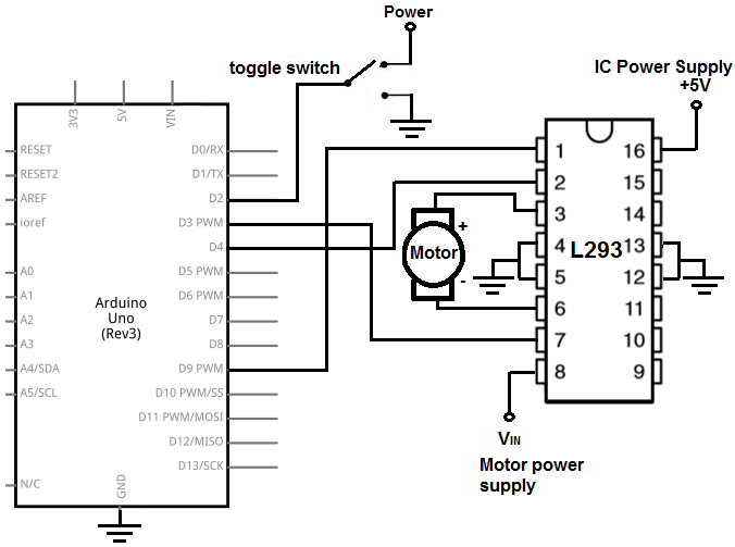
Conventional H-bridge circuit |
Circuitry
The encoder input are connected to two pins: 2 and 3, configured as INPUT_PULLUP. As mentioned earlier, it may be better to pass there outputs thru an NE556 to add some hysteresis.
The motor is controlled using an H-bridge ( SN754410) controlled with three pins: enable, pin 4, A pin 5 and B pin6.
The code also include connections to two momentary switches for manual testing: pins 11 and 12, configured as INPUT_PULLUP.
Complete Indexer
A complete indexer requires:
- an optical referencing point allowing position zero to be determined after power up and to re-calibrate the position due to any tracking errors.
- a display, possibly four seven segment displays, to edit and select track positions
- two momentary buttons to select menu and sub-menu options
- menu items need to include aligning either end of the bridge to a track and rotating the track 180 deg.
The above components will cost much more than the encoder that enables indexing and the code to support the display, buttons and store/retrieve track positions from memory is likely to be much larger that the positioning code above.
Summary
It appears that an inexpensive encoder can support indexing on older Walthers turntables.