Stan has been behind our project from day one, currently he's got an injured back and is out of work but he is gratefully plying away at this build to help us promote the work we've been doing.
This image shows our DP 1089 pilot mated to a DP 6051 pilot sheet and our frame kit for the GP 34' Bolster series.
You can also see our DP 6099 MU & Pin Lifter Brackets.
Here is a closer view of the DP 6099. We have recently revised all of our pin lifters to add new EMD versions and also tighten up the center where it loops around the outer components.

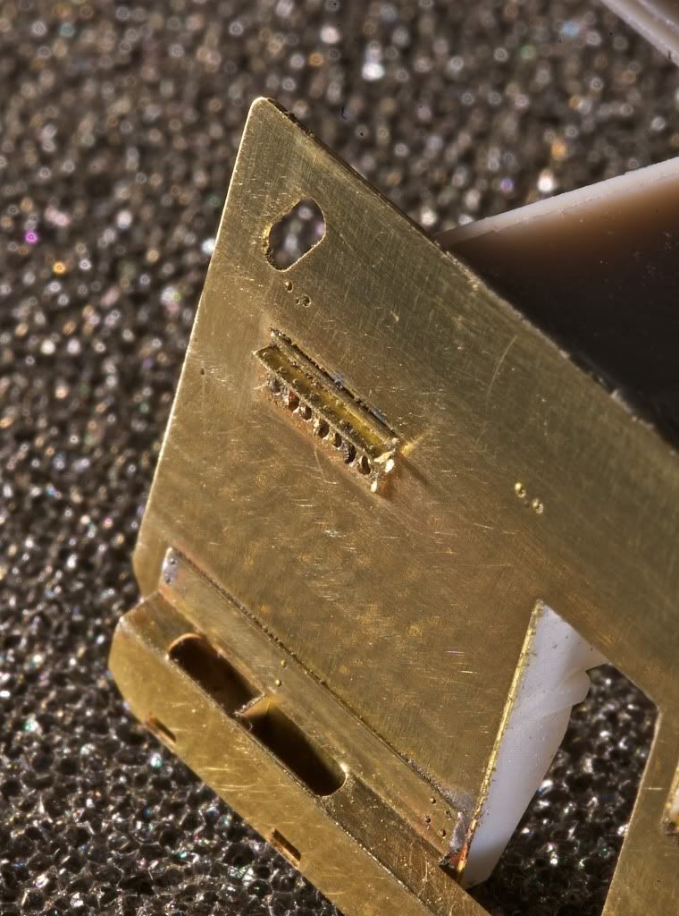
Next up is the addition of our pilot bracing, DP 6328 and the EMD steps, DP 6014. Using brass isn't that hard with a bit of practice. There are some new Microscale adhesives that work quite well and you can also use solder which makes the assembly bullet proof. The fine scale look definitely beats the look of plastic, every time.

Here is another view of the steps. We also have matching tread plates for all of our steps with various nose lengths, step wells, anti-climbers and such. Once the tread is over the deck, your seams disappear. The treads are ultra-thin so they are scale and they are also cut like the real treads so modification if needed for RTR models is a lot easier than having larger deck plates. The latest batch that came in January use bronze so there is no warp.

Next up is the under-frame bracing. The under-frame bracing, this is MK 7000, does two things. One it is a great detail part, and second, it gives you pilot locations for your under-frame details.
Trim below if needed.


All of the locations where marked as seen above. After doing this, apply the strip to the model.

This bit extra work with the marker ensures that everything will line up correctly when the under-frame bracing is applied.
Next use shims to add a bit of pressure while the adhesive dries.

Here is the applied bracing.

You are not done yet though. Sorry, but the pilot holes all have to be drilled.

So once you got the hole drilled next to the bit, remove the tab with a razor blade. The bracket you see to the right of the tip is what goes here.

Here is another area where the tab must be removed. The two half etched lines mark the location to cut.
You can add the DP 6215 traction motor circles next.

Use the DP 6205 pillow blocks and DP 6216 0.015" OD solder for your cabling. This last image shows the MK 4060 1700 US GAL fuel tank. Once it's on snuggly, there will be a scale inch gap between the top of it and the fuel tank. Just like the prototype. No motor to block the view, again, just like the real thing.

So we're trying to do a major sales push now to wrap up a number of projects. We have an entirely new electrical control system for our kits that includes prototypical lighting that has everything needed to use LED's and we're also using the best methods for motor control. The MCU can use either straight DC, DCC through the rails, or our new Tablet with the integrated Zigbee transceiver for control. Add a new Li-PO battery and you have an engine that just needs segments of track power to recharge. Recharge is three hours, battery life is about four without charging during operation.
Pre-orders only cover at most about 25% of the costs of these projects. This stuff is majorly expensive. We're very limited in resources but we've kept the sales that come inside the company. My volunteers and I are totally swamped with daily jobs and home life so its taken some time but we're almost there. So please bear with us, and continue the support. At this point we have hoods, trucks and a number of details in tooling. Our electrical system is starting the final round of design so its planned to be ready in May.
All the best,
Christopher Howard, President
Railflyer Model Prototypes Inc.
http://www.railflyermodel.com