Tom Patterson

This past week I completed the last of the hard shell scenery on the layout. I have worked my way around the layout in a somewhat hap-hazard fashion until all that was left to do was small portion of hard shell where the Wilson Bridge Branch leaves the room and heads to staging. The photo below shows the area with first pieces of cardboard webbing in place and the tunnel portal prior to weathering.

_720x480.jpg 


After weathering the tunnel portal with artist's acrylics, I applied plaster impregnated gauze over the webbing and covered it with Structolite. The photo below shows the area at this point.


_720x480.jpg 


The shot below shows the recently completed section along with North Pierce, WV. The area around North Pierce is the first area on the layout that was finished. It's somewhat ironic that this is also the first area that is going to be re-done. The main line here and the yard lead go into hidden staging and then heads to an unusable hidden storage yard. Also, the trees on the hillside here are from an old layout and I've found a much better way to make poly fiber trees. I attempted to replace the trees in this area but the scenery is just too deep- I can't even get to it with a creeper.
 

20x480_0.jpg 

Planned changes include having the hillside behind the factory extend to the wall and the yard lead joining the main just past the road. The main line will then proceed into a tunnel, through the wall and into the new 12-track staging yard that will be built in the other room. A few more pictures and a description of the new panel at CX Cabin can be seen at: http://cwerailroad.blogspot.com/.

Tom Patterson


Reply 0
Joe Atkinson IAISfan

Congratulations

Congratulations on the accomplishment Tom!  That's quite a feat.  I hadn't noticed the link to your blog in previous posts, and just finished paging through all of that.  Very impressive!

It's amazing to me that, if I'm understanding things correctly, the CWE locations are completely freelanced. You've shown some outstanding powers of observation and attention to detail to have created these scenes out of your imagination and have them look as realistic as they do.  One example that struck me was your access roads for things like signal boxes.  Not a detail you often see, but they're very well executed, and they go a long way toward enhancing the realism of the layout.

Any chance you could ever give us an overview of CWE motive power?  I noticed a few units in your blog that I'd never seen before.  I always appreciated the family look you achieved by mounting your bells on the rear of the long hood.

Reply 0
arthurhouston

My LAst Use of Any plaster was in 80s

Great looking layout and scenery. With this type of tree cover hills, styrofoam and cal coat 127 in the 21st century is the only way to go. I band paster from my layout room in the 80s. like DC it time to move on up. Their is ton of free large cell white foam out in the world laying around you can say you your layout in green because you recycle. Visit http://www.grandepacificmodelrr.org lots of examples of foam and cal coat 127. If you can't find cal coat 127 I will locate a distributor for you. It is a industrial insulation product. No mess , hours to work it. Foam is a good base for sticking tress in.
Reply 0
Benny

...

I do like the hollow factor of hardshell - you can get behind it and all sorts of things.

--------------------------------------------------------

Benny's Index or Somewhere Chasing Rabbits

Reply 0
JerryC

About those trees....

Can you tell us about your better way to make those trees Tom?

Jerry

Reply 0
Tom Patterson

Re: Comments

Joe- thanks for the kind comments. Everything about the Chesapeake, Wheeling & Erie is freelanced, although I have "borrowed" a lot from the prototype. For instance, the paint scheme on the cabooses is almost a direct copy of the N&W scheme in the 1970's. Many of the structures on the layout were scratch-built using standard C&O plans. The locations are all fictitious, but are based upon photos I've studied over the years. I'm not sure which engines you are referring to, as all of the motive power on the layout has been available in the market at some point over the years. Thanks for the comment about the bells- that's one of those little details that I added in an attempt to achieve the "family" look. While others may have noticed, I think you are the first person to every comment on them.

Jerry- sorry I missed your question in the previous post. I take a small clump of poly fiber and stretch it out into a thin, wispy length of about two feet or so. I then gently bunch it together- the trick is to not roll the material into a ball. This produces a number of different shapes in the material as you can see in the photo below.

_720x480.jpg 

The next step is to grab the poly fiber tuft in the center with long needle nose pliers and spray it with adhesive- I use 3M Super 77 Multipurpose Adhesive. Once the tuft is covered with adhesive, I hold it in a coffee can full of various colors of coarse ground foam and shake the can and foam around the tuft. The key is to make sure the tuft remains suspended in the can so that it keeps its unique shape. If you drop the tuft into the can or roll it around on a tray, you will lose the unique shape and end up with a ball. The photos below show some of the unique shapes you can achieve with the method.

c_0012_0.jpg 

gp7.jpg 

I take care when placing the tufts on the layout to make sure that the shapes and colors vary. Sometimes I'll end up after a session of applying tufts with several that didn't work from either a color or shape perspective. I just save them for the next session. The photo below shows a section of the layout after one such session and shows the basic process.

_720x480.jpg 

I also use Super Trees and other commercial trees in areas where I want to transition more gradually to the tufts as you can see in the photo below.

_720x480.jpg 

Let me know if you have any other questions.

Tom Patterson

Reply 0
Joe Atkinson IAISfan

CWE motive power

Quote:

I'm not sure which engines you are referring to, as all of the motive power on the layout has been available in the market at some point over the years.

I was just referring to power I hadn't seen on the CWE before perusing your blog yesterday.  The C628, six-axle U-boat, SD35, and EMD SWs were new to me.  All I'd previously seen were EMD Fs, GP7/9s, and SD40-2s - not that there's anything wrong with that - those are some of my all-time favorites.   Anyway, it made me wonder what else you have on the roster.

Quote:

Thanks for the comment about the bells- that's one of those little details that I added in an attempt to achieve the "family" look.

I think you're demonstrating an important lesson for proto-freelancers:  Choose a unique but noticeable detail location that prototype roads never used, and apply it to every unit.  To me, doing so is a subtle but effective way of validating your prototype's existence.  It's almost as if you're saying, "Of course this prototype existed!  Where else would I get the idea of putting the bell at the top of the long hood?".

To other proto-freelancers who might wish to consider this:  For ideas on what I'm referring to, look at nose gongs used by the CNW and DT&I, the Soo's practice of mounting horns on the angled portion of the cab roof above the engineer, the number plates the MILW welded at the top of the long hood side behind the DB blister, or the B&LE's inset sand fill hatches in the nose.  I'm not suggesting that you copy exactly what those roads have done, but that you give it your own twist, maybe mounting a gong bell in the side of the short hood, or offset to one side on the front, inset into the nose?

Unit number locations are another opportunity for proto-freelancers to demonstrate this identity, by putting them in a unique but consistent location, such as on top of the flat cab roof surface to make them more visible for tower operators.  Or maybe a small vertical plate could be added atop each unit for that purpose (something I think the Union RR did, IIRC, but you could choose a different location).  CP painted the unit number across the end of the long hood, but I don't recall any road that's ever done so on the short hood, so there's another possibility.

Even small roads with limited budgets often have telltale family details, but due to the often secondhand nature of their rosters, they may appear more gradually over time as units are shopped.  On my prototype, back in their more lean days before they started buying new power, one such detail was the appearance of round short hood vents on the right side of the nose, such as seen in the examples below (photos by Nathan Holmes and Erik Rasmussen).

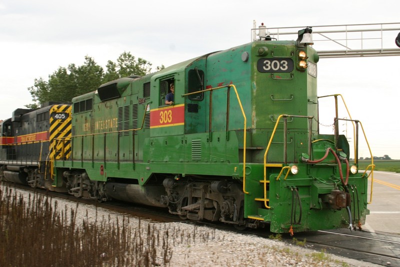
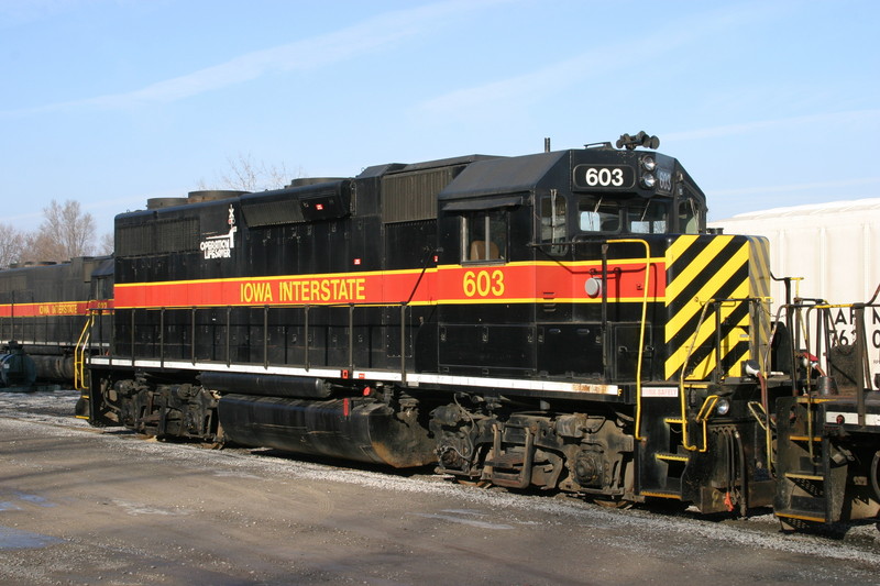
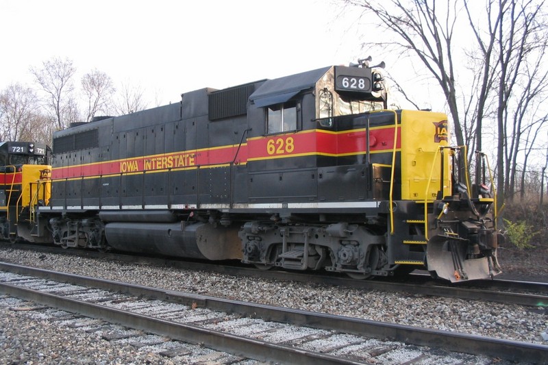
Other family details of IAIS units can be seen in the photos above:  Their practice of painting the receptacles on the outer MU hoses orange, and on the 603, the "Work Safely" sticker in the step well.  The latter was a part of virtually every IAIS repaint up until the late 1990s, but then fell out of favor.  The 303 and 628 both had their front step wells repainted as part of touch-ups done in 2004, so both lost their "Work Safely" reminders then.

For proto-freelancers, I think the important thing is to make the location of the detail something readily noticeable, but also somewhere that no other road has used before.  Finally, come up with a reason for the decision.  A railroad's Chief Mechanical Officer wouldn't make a decision like this, one that would cost money to implement, without having a good reason.  Tom never said why he chose to mount the bells on the rear of his long hoods, but I could see that making sense as a way to keep them clear of snow, while still leaving them high enough that they're easy to hear.

Anyway, I'm sorry to go off on this tangent Tom, but I think you've set a great example for other proto-freelancers, and one that deserves more attention.

Reply 0
pldvdk

Scenic Shell

Tom,

Congrats on the last bit of hardshell scenery! I'm in the process of just starting the hardshell scenery on my own layout, the N&W Pokey District, Sub 1 3/4 (formerly N&W Coal hauling layout). I don't have all the track down yet, but the current unavailability of Atlas code 83 flextrack forced my hand, and I needed to do something to keep construction moving forward.

A few questions on your scenery technique:

1) I have some rather large mountains going up on my layout. (See pics) How far apart do you put supports for your scenery? I've got the cardboard web up with some 2" masking tape covering right now, but it seems a little more "flexy" that I would like it. Will that change once the hardshell is on? I plan on using Joe Fugate's hardshell mix as a covering over the tape. 

_314x236.jpg _314x236.jpg 

_314x236.jpg _314x236.jpg 

2) Are the rectangles I see in your scenery forms access hatches? There seem to be quite a few of them. If so, how do you support these hatches? How do you take them off without messing up the poly fiber trees on top of them? Why are there so many? Are there tracks below these mountains that you need access too?

Thanks! And keep up the great work! 

Paul Krentz

N&W Pokey District, Sub 1 3/4


Paul Krentz

Free-lancing a portion of the N&W Pocahontas "Pokey" District

Read my blog

Reply 0
bear creek

Hardshell thickness

If you use a 1/4" thick layer of plaster and vermiculite (ala Joe Fugate - I don't use portland cement in the mix), it is very rigid and hard when it sets. I mix it in batches that cover about 1.5 square feet.

The biggest problem you'll have will be supporting it while it's still wet. For that you might want supports every 16" or so.

Charlie

Superintendent of nearly everything  ayco_hdr.jpg 

Reply 0
Tom Patterson

Re: Motive Power

Joe,

Clearly I missed the point of your question- sorry about that. I developed the roster back in the early 1980's when I first settled on the location and theme of the railroad. It was based on what prototype railroads were using in the coal fields in the 1970's, what was available commercially and what I liked- and pretty much in that order. In addition to the bells on the long hoods, I also make a point of using a limited number of horns and using specific horns for specific units.The roster has changed a little over time, i.e. I'm adding more GP7's and 9's than I had originally planned and there will be a few more six axle U-boats and Alco's, but the framework remains pretty much the same as I originally planned. Perhaps a future project will be putting something together that outlines all the influences, the decisions and more of the details as to how the roster developed. 

Tom Patterson 

Reply 0
Tom Patterson

Re: Scenery

Paul,

I am not familiar with Joe's method, so I'll defer to Joe and Charlie as to the support requirements.

Yes- the rectangles are Styrofoam access hatches and there are six of them on the layout.The two that are shown in this post provide access to a double crossover and two stretches of track that lead to staging in the other room. There is another one in the hillside behind the engine terminal, and this one provides access to lay the track in the roundhouse. Once that's completed, it won't be used as I can reach everything in this area with a creeper. The remaining three are small hatches mounted along the wall where the Sand Fork Branch is located and they provide access to switch machines.

The picture below shows how the hatches are mounted. I used two pieces of 5/4 to span the distance from the plywood to the backdrop and then glued scrap pieces of plywood to them to hold the hatch. I also framed the top and bottom with 5/4.

_720x480.jpg   

Removing the hatches will disturb the trees, but the plan is to use them as little as possible. The real lesson here is to make sure that you can access all of your track, and relatively easily. I learned that the hard way, and if I had to do it all over again, I would make sure that access to track was at the top of the list in terms of design requirements.

BTW- you're making fantastic progress. Keep posting the updates- it's fun watching this layout come to life.

Tom Patterson

Reply 0
Joe Atkinson IAISfan

Roster

Quote:

Clearly I missed the point of your question- sorry about that.

No worries Tom.  I always enjoy our exchanges.

Quote:

In addition to the bells on the long hoods, I also make a point of using a limited number of horns and using specific horns for specific units.

Good call there!  My prototype has done the same, moving toward standardizing on Nathan P3s for all but the new GEs.  Are you using sound?  It's amazing how this horn standardization is driven home by the use of sound...especially when you hear one of the units still equipped with a non-standard model.

Reply 0
wp8thsub

Progress

Congratulations on installing the last of the scenery shell.  I'm always interested in comparing and contrasting how layouts look at this stage of scenic finishing.  Our prototypes force us to do certain things, and allow us to get away with others.

Rob Spangler MRH Blog

Reply 0
Tom Patterson

Sound

       Are you using sound?

Yes- I am in the process of adding sound to every consist on the layout. The improvements in sound decoders over the past 3-4 years have been amazing and I really enjoy the choice of horns with the Tsunami decoders. I'm using Nathan M3's for most of the 4 axle units, M5's for the F-units and Leslie RSL-3L-R's for the six axle units. I have installed 5 Tsunami's over the past 6 months and am very please with the results. A number of other units have older Soundtraxx decoders in them. Once I started operating the layout, it became apparent that having a sound unit for every train would make a big difference in the overall experience.

Tom Patterson

Reply 0
Leo Starrenburg

Poly Fiber

I really liked the article about the trees and want to try it out, but what do you mean by "poly fiber" Tom ?

Where should I look for it ?

cheers, Leo


Farmers & Bluestone Railroad, a small On30 layout located in The Netherlands


Reply 0
rickwade

Poly fiber source

I hope Tom will forgive me for jumping in - here's Poly Fiber from Micro-Mark, a MRH advertiser:


olyfiber.jpg 


They also have it in black, which I prefer as it appears to give more depth.


Rick

img_4768.jpg 

The Richlawn Railroad Website - Featuring the L&N in HO  / MRH Blog  / MRM #123

Mt. 22: 37- 40

Reply 0
Tom Patterson

Poly fiber

Glad you jumped in, Rick. I purchased a large quantity of 100% polyester fiberfill from Putnam Company in Walworth, WI back in 2007. It came in 8 oz. bags, and one bag will do a large number of trees. I checked their website and it appears they no longer sell i, but I'm sure there are other sources of the same material that you could find on the web. And like Rick, I purchased the material in black,.which does help provide some depth. I haven't tried the material from Micro-Mark but it appears similar.


Tom Patterson

Reply 0
along

Motive Power

Tom      Like Joe  I also would like an article on your motive power and possible roster of your current units. I also remember in a post on your new at the time Alco C628, you were wanting to start posting video of your trains operating on the layout. Any chance of that happening any time soon?   Andrew

Reply 0
Tom Patterson

Re: Motive Power

Andrew,

The story about the motive power is in the works- it will show up either on the blog or, if it appears interesting enough and is accepted, in MRH. And I'm still planning to do some video- I just need to take the plunge and get a new video camera.

Tom Patterson

Reply 0
along

Motive Power

Thank you Tom      I look forward to both reading and seeing your stories that you'll be telling when they are ready. Andrew Long

Reply 0
Reply