MyIdaho

Just found out today that Duncan McRee, owner of Tam Valley Depot, has retired due to illness and their product line is going to be markedly reduced...  Very sorry to hear of Duncan's diagnosis, retirement, and business decision to reduce their product line.

I find the Tam Valley system to be very desirable for a newbie like me.  Pretty straightforward to adopt using servos for turnout control and have turnout location readily presented on the fascia.  I procrastinated too long before making an order.  The fascia controller kits for turnouts and constructed crossover fascia controllers are getting hard to find.  Tam Valley does provide circuit diagrams for alternative inputs but I don't know how to interpret the diagrams.  I would like to use toggle or pushbutton inputs and LED indication of turnout location.  Can someone help me interpret their diagram and describe how to accomplish on/off input and turnout location?  The diagrams are shown here:

https://www.tamvalleydepot.com/oldoctopusservodriver.html    scroll down

My initial paragraphs maybe asking for too much information...  Can someone answer if I can use a basic fascia controller to operate a single crossover?  Two servos can operate a single crossover, a single fascia controller can operate two servos so it should work.  The crossover controller operates the turnouts and shows which track is available with the LED's.  I can live without LED indication... 

Reply 0
Prof_Klyzlr

Yes

Dear Idaho, 

Darn, sad to hear about Duncan's health issues and retirement. Hopefully the Frog Juicers find a way to keep-on being available...

As far as your X-over is concerned, you sound like you've pretty much got it nailed.

- a TVD Servo Controller can drive 2x servos

- assuming you have the servos physically mounted so the throw direction and end-stop positions "work" _mechanically_ for both turnouts in the X-over, it should be "plug n play"

- if you need one of the servos to move "the other way" than how it does by default, _and_ its _impossible_ to physically rotate its mounting 180 degrees, then check in with the RC aircraft guys. They have plug-inline "Servo direction inverter" modules which will "flip the direction" of the incoming signal.

- Assuming both turnouts are throwing "as one" (per above), Then I would think that mounting the LEDs on a schematic diagram would be relatively easy.

IE

* The RED LED for "diverging"/"X-over" route is mounted between the 2x turnouts

* a _pair_ of GREEN LEDs for "normal"/"straight" routing are wired in parallel, and each is mounted in the "straight route" on the diagram

Sounds imminently do-able...

Happy Modelling,

Aim to Improve,

Prof Klyzlr

Reply 0
HVT Dave

Fascia Controller

@MyIdaho

That is some sad news about Duncan, thanks for letting us know.  He has been a great help to me for many years.

This circuit will control the servo with a push switch and LED indication.  Pressing the switch will toggle the servo position.  I have used this same circuit on several of the Tam Valley Quad Servo Decoders and it should work the same way on the Octopus.  Let me know if you have any questions.

ntrol(1).jpg 

BTW are you from Idaho perchance?

Dave

Member of the Four Amigos


Reply 0
oldmanep

Tam Valley

The notice from Tam Valley also listed that Jack Eiremann passed do to COVID.  They have listed those products that they will maintain on their web site.


Reply 0
MyIdaho

Thank you Prof Klyzlr and

Thank you Prof Klyzlr and Dave for your very helpful comments!  Unfortunately, I didn't search for Octo III's before making my post.  Sadly, I can't find any for sale so I need to put TVD aside...  Woulda, coulda, shoulda ordered a couple of years ago when I first contacted Duncan but wasn't ready to pull the trigger.  My main reluctance was having to spend lots of time under the layout setting up the servos (bad knees and not very limber anymore).  I found an interesting video that demonstrated surface mounting servos on a test track and thought maybe surface mounting would work for me if I can hide servos in buildings and if I can run the servo wire through a brass tube over to the turnout.  The brass tube would be just below the surface without affecting the scenery.  Is that an idea feasible with a servo?  If so, any limitations such depth below surface and run from servo to turnout?  The video is here: 

   Is there another easy way to control the servo, similar to the TVD Oct III controller board?  I've read and watched videos on arduinos but find it too complex for me...  A man's gotta know his limitations!  LOL

Dave, I live in eastern Idaho (Idaho Falls).

Reply 0
Prof_Klyzlr

Wire in Tube...

Dear Dave,

Quote:

I found an interesting video that demonstrated surface mounting servos on a test track and thought maybe surface mounting would work for me if I can hide servos in buildings and if I can run the servo wire through a brass tube over to the turnout.  The brass tube would be just below the surface without affecting the scenery.  Is that an idea feasible with a servo?  If so, any limitations such depth below surface and run from servo to turnout?

Sure, "Wire in Tube" has been a turnout-operation technique in the UK for decades, with "the thing doing the push/pulling" being everything from fingers, thru Caboose Industries groundthrows or solenoids, to servos and stepper-motors. As long as you take care not to get glue in the tube while ballasting (HInt: use full-strength PVA+ballast to create mini dams around each end of the tube, before doing the "mass dilute PVA flood" ballast application), you should be able to achieve a quite-frictionless movement-transfer.

As for length, K&S brass is available in lengths up to 3', so that's one "limiting factor"
Personally I've run over 12" from layout-fascia to turnout using regular-length K&S brass W-i-T with no issues...
(apologies for the poor image, CI 218S ground throws via K&S W-i-T to PECO turnouts)

hrows_01.jpg 

NB that with either CI ground throws or Servos, removing the over-centre springs from the turnouts will (very) likely be required.

Happy Modelling,
Aim to Improve,
Prof Klyzlr

PS I tend to use Foamcore extensively for my layout benchwork, so routing trenches for the brass tube "just below the surface" is childs-play...

Reply 0
HVT Dave

Servos and Arduinos

MyIdaho,

Arduinos are ideal to control servos and are actually easier to wire than the TVD fascia controller.  And as the Great Prof says, they will work just fine thru a brass tube to a nearby building or switch box.

When you get ready to go I would be glad to help you with a wiring diagram and the sketch (Arduino program) specific to your layout.

BTW I was born just down the street in Blackfoot, but have been in St George since 1960.

Dave

Member of the Four Amigos


Reply 0
MyIdaho

Follow up question

Prof Klyzlr, enjoyed your picture and your comments!  I do enjoy using CI ground throws on insulation foamboard, they are reasonably priced and generally maintenance free!  Wire in tube is very easy with foamboard.  Part of me is tempted to just stay with CI ground throws on the new layout.  Of course, they are oversized and get cause scenery problems when reaching to throw a switch.

Awesome offer HVT Dave!  The new layout is still rattling around in my head, simmering, waiting to try some things when the benchwork is up.  It will be a switching layout in an industrial area, operating single trains at a time.  Solo operation.  I can say that at this time, I am only potentially interested in using arduino + servos + pushbuttons to control turnouts.  LED indication of route would be a nice to have but not a gotta have...  Curious, given my interest, any recommendations by you and Prof Kyzlr on what I should consider buying to set up a small test section and play with arduino, servos, and pushbuttons?  Thank you for your thoughts and advice!

Reply 0
Prof_Klyzlr

Testbed for "small industrial switching" + arduino projects

Dear Idaho,

Quote:

Curious, given my interest, any recommendations by you and Prof Kyzlr on what I should consider buying to set up a small test section and play with arduino, servos, and pushbuttons?

For slightly different reasons, I'm also considering building a "testbed" modular switching layout at the moment, so your question is both timely and poignant for me. Given this, I'm going to jump out ahead of the curve and say

If you're looking for a "chainsaw"
(IE a Testbed which has "a representative example of everything you want to test",
and is only required to stand-up long-enough to fully-fease the stated experiments,
...if it happens to outlast it's originally-intended mission, then that's great)

then I'd suggest combining:

- a Foamcore "domino" module
(or similar "shelf" type plank, although Foamcore makes running wires,
mounting buttons and controls, and temporarily bolting-in various electroni boards and components a doddle)

- with a Lance Mindheim "No Skills, No Problem" layout
https://lancemindheim.com/2012/12/no-skills-no-problem/

OR

a Lance Mindheim "Practise Plank" layout
https://i.pinimg.com/736x/05/82/fd/0582fd87d44e457ba9dbc015602ee110--ho-scale-model-train.jpg

OR

a Isaac Fabris "one turnout" layout
https://www.facebook.com/photo/?fbid=769808487105505&set=gm.3335805259817952
/> (for the FB fans)


The key in the above options is that there is:
- a turnout (arduino turnout-control + servo experiment)
- a grade crossing (arduino detection + Xing lighting + possible servo gates + possible sound experiment)
- an industry (lighting and triggerable arduino animation opportunties ahoy!)

- and enough track to provide a very Lance M-esque "slow and purposeful" local-industry switching op session,
particularly if you take Lance + Isaac's words of wisdom RE "car spot switching"
(IE there is actually more here than "just a testbed plank" or "zero-operation potential" static diorama).

...while not chewing up a lot of time/$$$/effort, so if the "experiments" don't prove forfilling,
you haven't wasted much-at-all, and can quickly and painlessly refocus onto "more satisfying projects"...

...and with Lance's "Skills Builder" directions guiding you,
the resulting "switching plank" can even look quite finished and impressive to "passers-by" in short order...
(IE what started conceptually as "just an experimental testbed" platform layout,
with no particular Aesthetic or Operational asperations,
could well visually + mechanically + electrically + operationally out-perform all initial expectations,
and "hold it's own" as the launchpad component of your new "real layout"...   ).

Happy Modelling,
Aim to Improve,
Prof Klyzlr

PS it's tenuously related, but I would suggest checking out the "$500 Layout Challenge" entries from a few years ago (Plug "$500 layout" into the Search box at Top Right of this page),
specifically https://model-railroad-hobbyist.com/magazine/mrh-2013-09-sep/layout-chicago-fork
(It wasn't specifically a testbed for Arduinos, but it did act as a testbed for a number of other experiments and provable concepts, inc "W-i-T with CI groundthrows"... )

Reply 0
MyIdaho

Wow, Prof Klyzlr!  Excellent

Wow, Prof Klyzlr!  Excellent reply and very motivating!  I appreciate the links!  For starters, I'd like to try the following:

1) a single turnout and a crossover using two servos

2) turnout servos mounted inside building with W-I-T to servos

3) mounting momentary pushbuttons singly and as part of a control panel

4) grade crossing gate with flashing light

5) lighting the loading dock area and an indoor office

What is the best way to get started, purchase a starter arduino kit or purchase just the needed parts?  In the long run, it is cheaper to buy bulk connectors and make your own connector wires at the appropriate length but prepared wires are easier for early experimentation.

Rick

Reply 0
Prof_Klyzlr

Where to start RE Arduinos

Dear Rick,

Honestly, if you're looking for "101" Arduino info,
I'd reccomend heading straight for the excellent work by our own Dr Geoff Bunza...

https://model-railroad-hobbyist.com/magazine/mrh2016-12-dec/arduino

https://model-railroad-hobbyist.com/node/42392

As with many "experimenter" projects, the rabbit hole can get pretty deep if you just jump in with a "let's see what is possible" mindset. Personally, I find it much better to start with a clear vision of what you want to achieve,
(This is where starting with the "One turnout layout" comes in,
it "sets the project-list, desired results, and sets some expectations" from the outset)

and then read thru Dr Geoff's article, and consider how the various basic concepts and examples could be applied to the specific list-of-projects your "one turnout layout" includes.

Once you've matched "actual projects" to "arduino examples which could forfill them",
the resulting "shopping list" of components required should shake-out and become reasonably self-evident...

Once you have a confirmed "shopping list", the actual purchasing can be done at-your-leisure thru whatever sources you're most-comfy with. Many Arduino-experienced modellers have their preferred sources, ranging from Amazon and similar, thru eBay and auction sites, to specialist Electronics suppliers like Mouser, DigiKey, Pololu, etc.

The one thing I would note is that the "One turnout Layout" is exactly as it's name suggests, 
there isn't a "crossover-pair" of turnouts for you to try your "One Servo Controller, 2x Servos" project on.

That said, personally, I would focus on getting a single-turnout working "one turnout layout" style,
getting one "complete" Servo + W-i-T + Turnout array working "from nothing" is the arguably hard part.
Achieve that, and you'll realise that doing a "ganged crossover pair" is literally
"...just do the same thing that worked before, again, x2..."
(Hint: there are differences and reasons why you might choose to wire 2x servos to the same single "servo signal",
OR
wire each Servo to it's own dedicated "servo signal" and let the Arduino software take care of "ganging them together"

in either case, it's still "one button push = 2x turnouts move simultaneously",
but the difference RE the arduino-driven bit in the middle is instructional, and a lesson worth working-thru)

Check out Dr Geoff's article linked-above, and go from there...

Happy Modelling,
Aim to Improve,
Prof Klyzlr

Reply 0
MyIdaho

Excellent, thank you Prof

Excellent, thank you Prof Klyzlr!  I was thinking that two servos + y connector wire to controller (per TVD design) was the only way to do it!  Will go with one turnout!  Will check out the links, again thank you for being so helpful to a newbie!

Rick

Reply 0
HVT Dave

One Turnout First

I totally agree with what the Prof says.  Take some time to study Geoff Bunza's instructions.  Get one turnout working correctly.

Then, with an Arduino you can use two outputs for the crossover allowing you to set the travel for each individual servo (settings will almost certainly be different) and in the software control them both with one button push.  (The 'Y' cable sends the same command to both servos, not necessarily the ideal situation for a crossover)

After you study Geoff's instructions and have the Arduino, feel free to come back here and ask for any help you may need.

One question that hasn't been discussed, how's your soldering skills?

Good luck going forward!!!

Dave

Member of the Four Amigos


Reply 0
Ron Ventura Notace

Berrett Hill have some great options.

I am controlling servos with an Arduino and the Touch Toggles from Berrett Hill  https://www.berretthill.com/controls/berrett-hill.html

They work a treat and you can mount them into a control panel to provide LED indication of the selected routes. But if you don’t want to go the Arduino route, Berrett Hill also have a range of boards to control the servos. Generally it’s a case of plug in the servos, plug in the toggles, power it up and go. Not sure of the cost, but they all look to be great solutions. But it’s worth looking at Geoff Bunza’s work.

Ron Ventura

Melbourne, Australia

Reply 0
MyIdaho

Ron, thank you for the

Ron, thank you for the Berretthill suggestion, link, and reporting your positive experience.  The touch toggles are very nice and make for an easy plug-and-play installation.  They are a bit on the pricey side though so must weigh cost versus labor, less time under the layout, sourcing parts, shipping, and ease of use.  Keeping things simple and minimizing time under the layout are both very important for me!

Reply 0
MyIdaho

Questions on Geoff's project

My primary interest at this time is planning turnout control.  The TVD product line was very appealing since it was designed for KISS guys like me with minimal electronics experience.  Duncan gave very complete guidance where I could easily plan turnout control for the layout in stages.  Overall, I would need 6 Octo III's, two power supplies, ~46 servos, 6 crossover controllers, and 34 individual turnout controllers. 

Now I have to go to a plan B and the primary focus is still on turnout control.  I downloaded Geoff's Dec 16 article and went to the section on servos and focused on the project with servos + switches + LEDS on page 37-38.  I'm a visual learner and was disappointed that I couldn't see the connections below the perf board nor did I have a good view of the labels for the connection points on the bottom of the sensor shield.  Can someone please explain the connections for the LED's?  On page 36, there is a single connection from the LED to 5v power and from the neg lead to a 10K resistor then to one leg of the switch.  Are there six individual LED connections to the 5 V power?  The LED's will only turn on momentarily when the button is pushed correct?   What is the dark blob on the upper left side of the perf board?

What size wire should be used and solid or stranded?  Solid 22 gauge wire okay?

In a practical application, where is the UNO + sensor shield stack located on the layout?  In front, below the layout seems best during installation for ease of access but in the back seems appropriate to minimize any disturbance or idle grandkid fingers...

I need to watch some videos that discuss how servo arm and servo body positioning influences turnout throw.  I will be throwing the turnouts from the side rather than from directly underneath.   It will be an interesting item to test when I receive some servos + uno + sensor shield.  There are so many different servos, unos, and shields out there...  Can someone give a recommendation(s) on which to purchase?  I have no prior experience with any companies or variants so I'm at a loss on how to choose?

That's all my questions for now...  Thanks for any assistance you can provide!

Best,

Rick

Reply 0
Ron Ventura Notace

For that many servos

Rick, to control that many servos, you’ll need more than a single UNO, because you run out of pins. You’ll need a pin for each servo, and another for each Touch Toggle (assuming you go that way). I have 12 servos/touch toggles and use two UNOs to drive them, which pretty much maxes out the pins. Arduino Megas have a lot more pins, but once the toggles are accounted for, I think you’d still need more than one.

I’m not sure, but I think you could get away with a single Mega for the toggles. And if you used PCA9685 PWM boards you could drive more than enough servos. Each of these boards can drive up to 16 servos, and up to 62 of them can be daisy chained for a total of 992 servos. You’d need to provide 5v to each of the boards to power the servos, probably by providing a separate 5v bus. I have a 12v, 5Amp bus running the length of my layout, and just use a buck converter to provide lower voltages where needed. 

This all sounds complicated but the connection to the PCA9685 from the Arduino is only four wires, as is the daisy chain. The servos and touch toggles use 3 pin connectors so are easy to hook up to the boards. (Use a servo shield for ease of connecting the toggles). If you don’t like soldering, make sure you get the boards with the pin headers already attached. Some suppliers provide the headers but leave it to the buyer to solder them to the board. It pays to shop around.

I like the touch toggles because they provide the input switching, as well as led feedback for turnout position, all in a single package.

Ron Ventura

Melbourne, Australia

Reply 0
Prof_Klyzlr

Um, hold up a sec... (Start simple...)

Dear Ron, Rick

My apologies ahead of time Ron, but I fear you may be over-estimating Rick's current level of Arduino knowledge/familiarity/competency/need/requirements. In order of appearance:

Quote:

to control that many servos you’ll need more than a single UNO, because you run out of pins

How many servos? Rick has been counselled to do One Servo as a starting point. Dr Geoff's projects allow Six to be handled by either a single UNO or Pro Mini/Nano. Strongly reccomend Not forcing Rick to run before he's even considered what's involved in crawling...

Quote:

I have 12 servos/touch toggles and use two UNOs to drive them, which pretty much maxes out the pins. Arduino Megas have a lot more pins, but once the toggles are accounted for, I think you’d still need more than one.

Certainly true for "experienced Arduino Users", but this is Far Beyond where Rick is Now,
let's not scare the pants off him with Big Numbers and Large Arduino units just yet...

Rick, if I may, to achieve Dr Geoff's example projects in a "bench test" or "101 level" mode,
(which I would Strongly Reccomend, considering "wire sizes for long cable runs"
and "where to mount the boards on the layout" is a Long way down the track from where you are right-now...)

you need Only a basic Arduino UNO
(see below)

_Example.png 

OR a smaller Arduino Pro Mini or Nano
(Pro Mini on DIY Perf-board "prototyping board" shown below)

_Example.png 

Rick, Look carefully at the above,
(Right-click and "View Image in New Tab" to see _larger_ versions)

Note and compare the Image Text to the labelling on the Arduino PCBs,
(apologies, but on the UNO pic especially, the perspective-error makes it look like the black socketed-holes don't align with the solder-points/pins on the Blue Arduino PCB, but they do...
...it helps if you count up the socket holes, and count up the silver solder-points on the PCB, just to dbl-check...    )

then compare the labeled pins with the diagrams in Dr Geoff's article
(5VDC, GND, and "Input/Output Pins")

and you should have enough to work out "what goes where"...

Again, start with a Single Push Button/LED/Resistor INput and Servo OUTput pair,
(the software Sketch you load will not care that you're only using ONE out of the SIX that the Dr Geoff "6 Switched Servos" Sketch is configured to handle)

get that working,

and then we can extrapolate for bigger/better/more-complex things...

Happy Modelling,
Aim to Improve,
Prof Klyzlr

PS Most Modellers who have played wiith Arduinos have their preferred sources, mainly selected by Price, Availability, and Shipping factors. These range from Amazon and similar, thru eBay, to specialist Electronics/Arduino suppliers like AdaFruit.com , SparkFun.com , Mouser.com , DigiKey.com , and similar.
Got to prep for Night-shift right now, but can get some links together later if required... 

Reply 0
Prof_Klyzlr

Parts Sauce

Dear Rick,

Following on from earlier, you've prompted me to go hunting for "Arduino Starter Kit" options.

As a lead-in, I've tried to select the cheapest options I could find that were shipping from within Continental USA,
as current shipping delays and issues are some of the most effective "project momentum/motivation killers" I've seem in quite a while.

It should also be noted that it is always possible to find "a deal" somewhere, if you search the right-thing-at-the-right-time, are willing to be flexible with where the product is actually shipping from, or just "happen to get lucky". In the "electronics experimenters space", there is always subtle changes and evolutions in components and parts,
so expecting to buy "exactly the same thing" even weeks-apart is a fool's errand. Learning the Rules (basics of electronics) so you can known how and when it's permissible to "bend the rules" is key.

So, where do we start?

- You could search-for (and find) umpteen options for "Arduino starter kits", which include a representative set oif components. Kits such as this from eBay.com

https://www.ebay.com/itm/324107849059
(USD$36 + shipping)

will get you
* an Arduino UNO board + USB cable
(IE the barest minimum required to "load a sketch into an Arduino)
* a selection of jumper cables to wire things together "on the workbench"
* a couple of "pluggable breadboard" units to lay out components/buttons/LEDs
* a bunch of resistors, switches, LEDs, and a Servo
(IE the main "Input/Output devices" a model RRer is interested in working with)

and some other assorted interesting doohickys which might become useful to play-with once you're comfy with the "basics of Arduino" and want to extend your repetoire...
(EG Normal and Stepper motors, LCD displays, Ultrasonic and Temp sensors, buzzers, relays, etc)


- HOWEVER, if you're focussed on Dr Geoff's projects to lead your first steps, one key component you'll note is missing is a "Sensor Board".

"Why is this important? I mean, Prof, your own pics above don't show one..."

Well, while the pics above help reconcile the "which pin is which" against the fundamentals of Dr Geoff's example sketches (see the Dec 2016 article), connecting much more than ONE switch and ONE Servo DIRECTLY to an Arduino UNO may start pushing the power-supply limits of the Arduino itself.

By using the Arduino's "5VDC" and "GND" pins, you're loading down the Arduino's onboard power-supply circuitry with the "load" of the Arduino itself _and_ the additional circuitry. Add too much "additional circuitry", and things start not-acting the way you expect.

A Sensor board uses a larger, beefier PSU to provide seperate 5VDC and GND lines to power the "external stuff" (the LEDs and Servos), and leaves the Arduino's onboard power-supply circuitry to just worry about powerng, well, just the Arduino. This gives both "all the power you need, where you need it", AND allows the Arduino to behave in a more "stable" manner.

Look carefully at the example "YFRobot Sensor Shield" below, and you'll notice:

- The BLACK pin headers along the TOP and BOTTOM edges,
which match the UNO Pin positions/numbers in the images posted earlier
(zoom in and check the WHITE labelling of each pin)

- You'll also notice that accross the INSIDE of the PCB is a load of 3-pin-grouped connections.
These BLACK + RED + WHITE groups have "pin labels" which, looky here, seemingly match the "pin numbers" of the UNO pins along the TOP and BOTTOM edges.

EG At BOTTOM RIGHT you can see the "ANALOG IN - A0 / A1 / A2 / A3 / A4 / A5" BLACK pin header

and just above it you can see the matching BLACK / RED / WHITE "A0 / A1 / A2 / A3 / A4 / A5" set of pins.

d_Marked.PNG 

Follow around the board, and I'm sure you'll identify the other "pin <> pin matches"...

Hopefully it will have also dawned from the previous Arduino pics, 
plus Dr Geoff's article, 
plus the above pic,
that the "5VDC" and "GND" pins are required to be connected all over the place,
and yet the actual host Arduino only has a few of each connection available at best...
(This is why I put the horizontal groups of 5VDC and GND connections on my "Pro Mini DIY Breadboard" posted earlier...)

The Sensor board provides a dedicated physical 5VDC and GND connection for each of the Arduino pins it "breaks out", making connecting diagrams such as the "LED + Switch" part of Dr Geoff's "6 switched Servos" project a lot simpler. (Each "LED + Button" set needs a 5VDC + Signal-Pin + GND set of 3-connections, and the Sensor board provides all 3 pins for you, right there... ).


"...hold up a sec Prof, how does this Sensor board connect to the Arduino? Do I have to wire a load of jumper wires between them?"

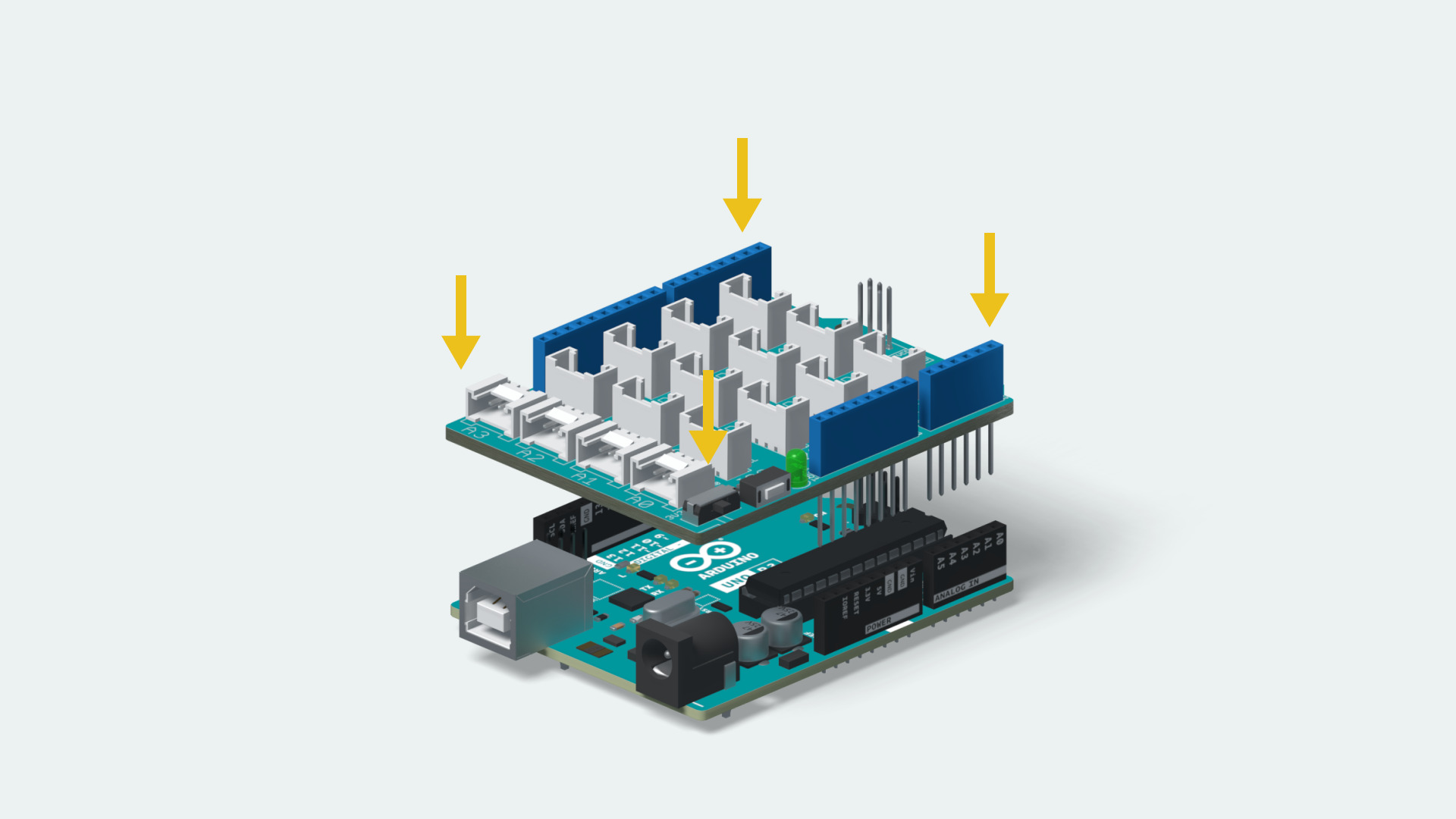
Um, no. The beauty of the physical Arduino "Form Factor" is that "shields", the terminology-name for bolt-on boards such as the Sensor board, simply plug into the Arduino Uno as shown below...


"...sooooo, we've come a Long Way from 'where do I buy stuff'....
what does it mean in $$$ terms?"

Well, as we started this post with, the prefab "All you need Arduino Start Kits" have a lot of useful stuff,
but without a Sensor Board, following along "pin for pin" with Dr Geoff's excellent examples might pose some challenges, like

"how do I get enough 5VDC and GND pins to connect everything up?"

and

"yep, it's all wired up right, but the Arduino is acting flaky with all the extra circuitry hanging off it's onboard PSU circuitry"

SOOOO, the other-end of the spectrum is to purchase "only the bits you need" seperately. IE

- An Arduino UNO
https://www.ebay.com/itm/254928538105
/> (USD$6.70 + shipping)

- a Sensor Shield
https://www.ebay.com/itm/383719978047
/> (USD$6 + shipping)

- an SG90 or MG90 Servo
https://www.ebay.com/itm/283522010547
/> (USD$4.45 + shipping)

- a "grab bag" of buttons/LEDs/resistors
https://www.amazon.com/LAFVIN-Electronics-Component-resistors-Potentiometer/dp/B077QPVXK9
/> (USD$6.50 + shipping)

- and some patching-wires
https://www.ebay.com/itm/253824729484
/> (Make sure to choose "Type = 'All 3'" Less than USD$8.00 + shipping)

(Total of approx USD$32 + shipping)


...and, of course, if you wish to spend a little time with eBay, Amazon, adafruit, SparkFun ,
you may well be able to snag some better prices "in the moment"...

Anywho, that should be enough to set you off and hunting for the moment...

Happy Modelling,
Aim to Improve,
Prof Klyzlr

Reply 0
Prof_Klyzlr

Example...

Dear Rick,

FWIW... (I didn't have a Sensor Shield handy, but oh-well....   )

Happy Modelling,
Aim to Improve,
Prof Klyzlr

Reply 1
MyIdaho

Wow, super!  Very, very

Wow, super!  Very, very helpful!  You have a very motivating, inspiring teaching style!  Ordering now!  Can't wait to start the "hands-on" learning curve!  You're the best Prof Klyzlr!  You're teaching an old dog, retired, dairy management consultant, new tricks!   

Reply 0
MyIdaho

I have received multiple

I have received multiple suggestions to start learning use of an Arduino with just one turnout.  I'm using Dr Geoff's article entitled "A Modeler's Introduction to Arduino" as a guide.  I am primarily a visual learner so I found his article, pictures, and sketches very helpful.  However, I still wanted a more practical application view rather than prototyping view using breadboards.  I found an excellent youtube video by Rob the nscaler which provided visual guidance with practical application.  Kudos to Rob for a job well done!  The youtube video can be found here:  

   Rob built a simple test setup with one turnout, a servo, and a mini control panel:  

image.png 

Rob's wiring diagram for this project is shown below

image(2).png 

Wiring for Rob's control panel is shown below.

image(3).png 

The IDE sketch for Rob's project and construction + design details are presented at the link below:

http://thenscaler.com/?page_id=174

A diagram of Geoff's project switch from his Dec 2016 MRH is shown below.

image(4).png 

Geoff's sketch

//   MRH One Switched Servo
//   G. Bunza 2016
//
#include < SoftwareServo.h>
SoftwareServo servo1;
#define  control_pin   14     // D14 (A0) has a Switch to ground
#define  servo_pin     3      // D3 has Servo
#define servo_start 20        // Servo start position
#define servo_stop  168       // Servo stop position
boolean saved_switch = false;
void setup()
{
  servo1.attach(servo_pin);
  pinMode (control_pin,INPUT_PULLUP);
}
void loop()
{
  // Sample the Switch 3 times to be sure
  if (digitalRead(control_pin)==LOW)  {
      servo1.write(servo_stop);
        for (int i=0; i< 200; i++) {   // Wait for servo repostion
          SoftwareServo::refresh();
          delay(1);
        }
    } else  {
        servo1.write(servo_start);
        for (int i=0; i< 200; i++) {   // Wait for servo repostion
          SoftwareServo::refresh();
          delay(1);
        }
    }
}

Some questions.

I like the idea of using two LED's to show turnout position versus a single LED.  Not sure what needs to change in Dr Geoff's single turnout project from Dec 2016.  Geoff only used one uno pin for an LED while Rob used two uno pins.  Rob's IDE sketch is significantly different the Geoff's.  Could someone show me what needs to change in Geoff's single turnout sketch to use two LED's?

A UNO can control 50% fewer servos when using two LED's to display turnout location, correct?

Rob used 220 ohm resistors throughout while Dr Geoff used a 10k and a 470 ohm resistor.  Huge difference in resistance values, which ones should I use?

A UNO can control 50% fewer servos when using two LED's to display turnout location, correct?  Or is there a workaround to operate the same number of servos per UNO?  I am a novice so will not understand a complex solution.

My future layout will be 60 ft long with approximately 42 turnouts. I am planning on splitting the layout into 5 to 7 areas with each area having its own UNO.  Two or three power supplies will be used to power the UNOs.  Bad or good idea in general?  Just trying to identify the Big picture understanding for my project.


Reply 0
kenheywood

QuadLN_S appears to still be

QuadLN_S appears to still be available from the Tam Valley website. It's a great alternative to the Octo.

Reply 0
MyIdaho

Thanks for the heads up!  I

Thanks for the heads up!  I see that the QuadLN_S is used for DCC control of turnouts.  IMO, manual pushbuttons are preferable for turnout operation and DCC is preferable to operate trains.  Thanks but doesn't fit my preferences.

Reply 0
Prof_Klyzlr

2x LEDs in Dr Geoff's "6x Switched Servo" example...

Dear Rick,

...Just because I had a few seconds to plug some jumper wires into a Breadboard while on night-shift...


NB: the RED LED _IS_ working, it's just a lot dimmer than the GREEN LED
when you/the-camera is not looking at it "end on"...

HINT: 
- Google "Voltage Divider" or https://learn.sparkfun.com/tutorials/voltage-dividers/all

- Remove 10K Ohm resistor from Dr Geoff's "Button + LED" array

- Connect pair of LEDs back-to-back
(you've picked up that LEDs are polarity-sensitive, yes?
Apply volts the Wrong-way-round and they do Not light-up)

- Connect one leg of the "LED Pair" to the "UNO pin" (UNO pin A0) of the Dr Geoff push-button switch

- Grab 2x 240 Ohm resistors, wire in Series (end to end)

- Connect one "end" of the "2x Resistor chain" to 5VDC

- Connect other "end" of the "2x Resistor chain" to GND

- Connect the Free leg of the "LED Pair" to the joint between the 2x resistors

...then power-on and press-the-button...

I sincerely hope this helps...

Happy Modelling,
Aim to Improve,
Prof Klyzlr

Reply 0
Reply