The Plymouth Switcher - CR-4
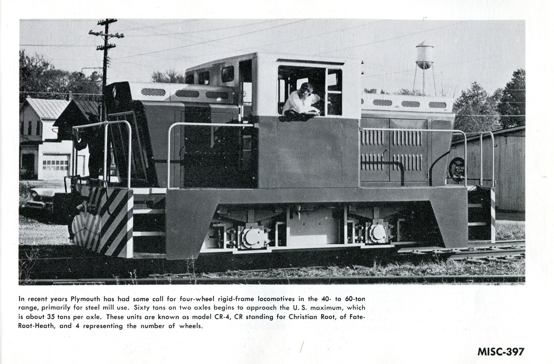
The Plymouth switcher CR-4. CR stands for Christian Root, of Fate-Root-Heath and 4 representing the number of wheels.
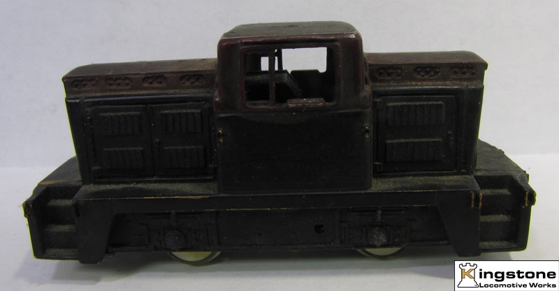
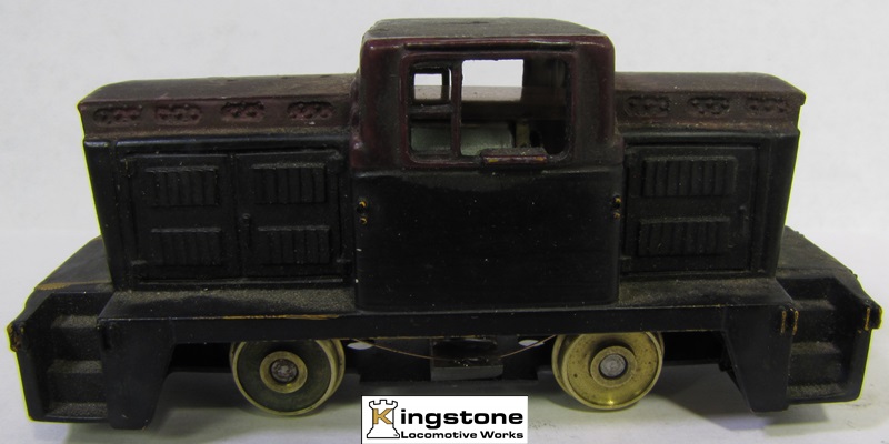
The model by Tyco.
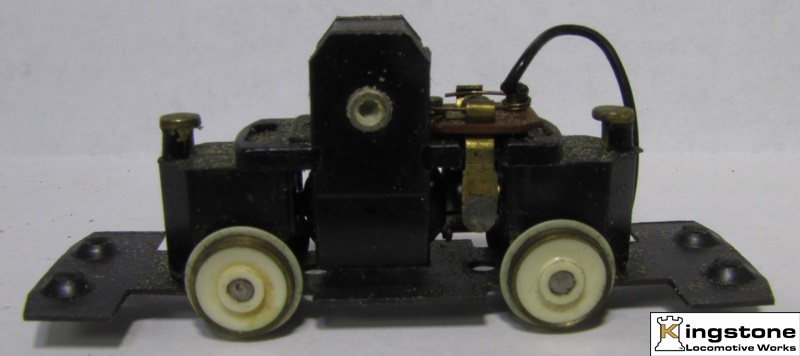
This is the disassembled model.

First remove the magnet by grinding out the rivet.
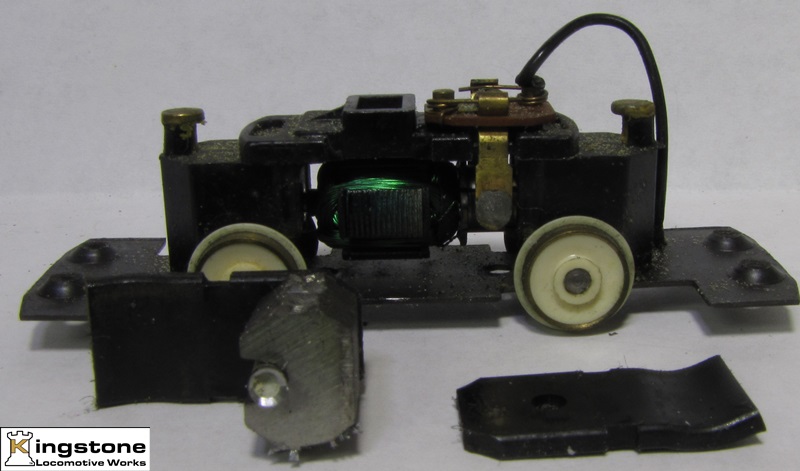
Next grind out the rivets holding the motor together with the bottom plate.
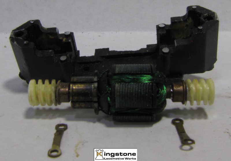
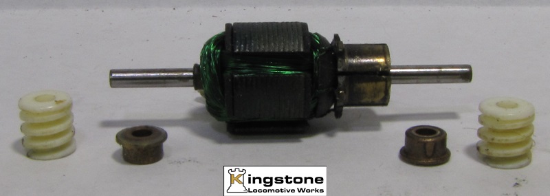
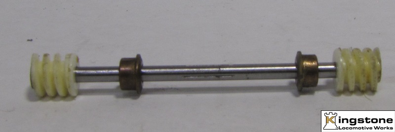
Remove the worms, bushings and commutator/wire armature.
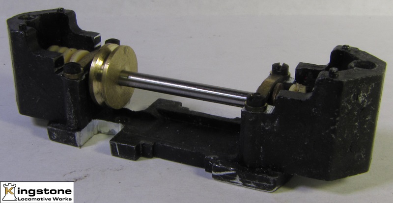
Next I drilled and tapped the holes to hold the brass bushing straps using 0-80 scrrews. Turned a pulley with a V groove for the drive belt. Also ground relieve slots for the belt in the frame.
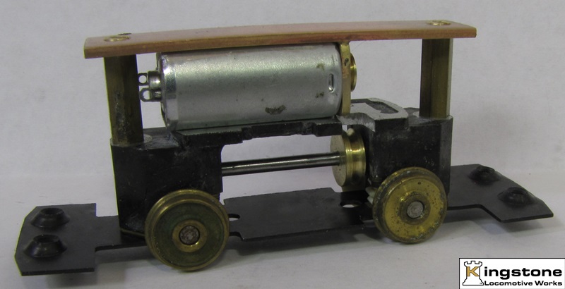
The motor is from a reduction drive. I used the one plate and a piece of brass to make a motor mount. Also a pulley was made and Loctited to the shaft.
A couple of pieces of octagon stock was used to make standoffs for the motor mount.
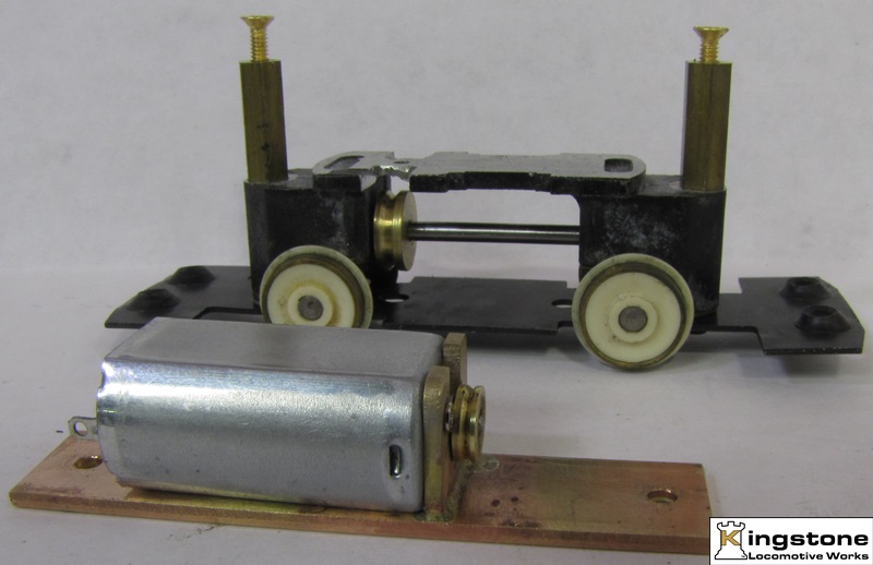
Test fit to make sure it all works out.
A piece of PC board is used to hold the wheels wipers. The wipers are made from .010" phosphor bronze wire. The belt has also been added.
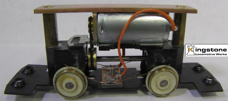
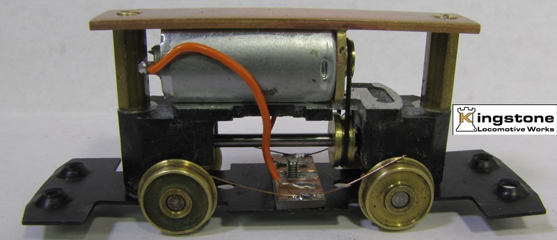
And the finished product.
Here's a video. The engine is run at two voltages, 4 volts and 6 volts. The motor is a 6 volt motor.
Next is Version 2.0. A different motor and mounting method.
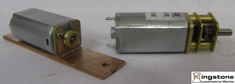
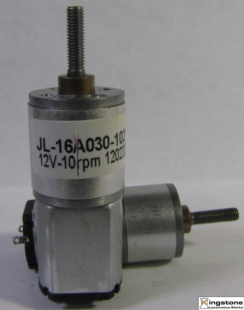
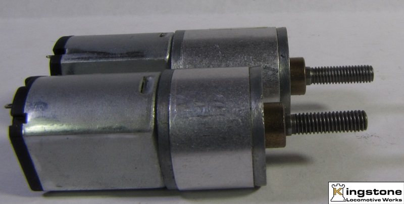
A fellow modeler alerted me to seller on E-bay that had motors I might be interest in. I took a look and sure enough it was something I could use. I ordered a lot of 10. But what I had no idea at the time is that the output shaft revolves at 10rpm at 12 volts. A bit slow. Here's what they look like.
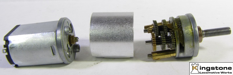
Taking the gearbox apart you get an idea of how a reduction gear drive works. It's almost like a standard transmission without the clutch. I think there are 6 stages of reduction. I removed the first three, plus I had to shorten some of the components in the gearbox to get it back together and work properly.
Here's one with the three stages removed and reassembled. The one in the back is unmodified.
The final result of removing the first four stages. I didn't bother with shortening the gearbox cover. The motor is epoxied to a brass motor plate and bolted on with the motor assembly bolt. The rest of the components are from the first version of the mod.
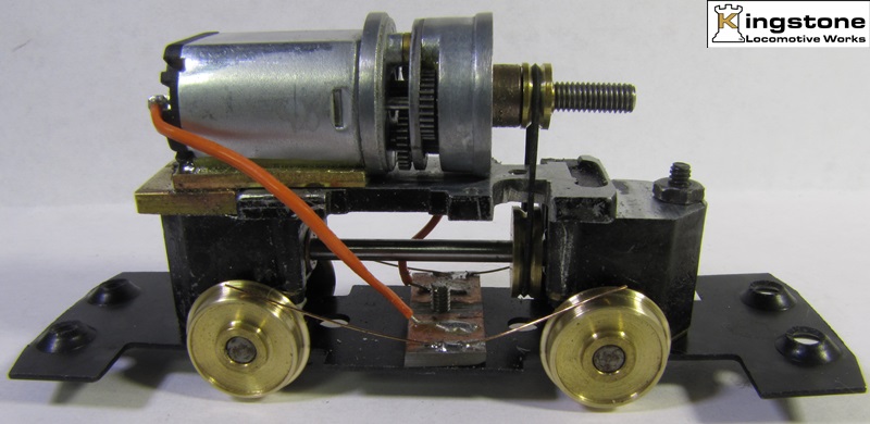
The pulley on the motor is easier to make and change do to the output shaft being threaded for a 3 X 0.5 mm thread. With this setup I can get it down to a crawl from tie to tie. Top speed probably is in the range or 5 to 10 scale miles per hour. I'm going to have to have a bigger pulley on the motor and a smaller one on the driven shaft.
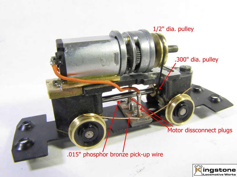
I wasn't happy with the speed of the engine. It just didn't seem fast enough at 12 volts. So I made two new pulleys, 1/2" dia. and .3" dia. I made plugs to plug the motor wire leads into. Makes it easier to disassemble and assemble the motor and frame. Plus I changed the pick up wipers to .015" phosphor bronze. I almost melted the .010" on the previous version when something jammed the in the gears and the motor stalled. Here's a picture with the up-grades.
And a video showing just the chassis running a 2.5 volts and then with the shell on pushing 8 hopper cars at 12 volts. Speed looks about right for a wide open throttle.
The engine was run on plain DC voltage. I have since added a DCC board. I tried running it today and the belt was slipping. Looks like it might have stretched.
These were all prototype experiments in seeing if it is possible to use better motors with reduction gearing or belt drives. The belts are neoprene. They have .090" square form and run in a "V" grooved pulley giving them more grip than a round belt. Further experimentation is needed to perfect these drives.
Bernd