mdavidmerrill

13 Benchwork

With the helix in place it was time to expand the benchwork. For those who may be new to model railroading the benchwork is the table that holds the model railroad. However in this case the management want flexibility for scenery. This means that we will use an open table consisting of support beams and open joists to which we will fasten the track and the scenery. With an open grid the scenery can extend below as well as above the top of the table. With a flat table top the scenery can only extend above the scenery.

The side of the benchwork against the wall is supported by TGI beams. These are beams that are usually used for floor joists. The advantage is that they are strong and can have a long span without supporting legs. We placed the TGI beams around the walls supported every 8 to 12 feet by a 2x4 leg that extends up past the TGI beam and thus supports the backdrop framework. (See post #7).

The front of our benchwork (table) is formed with an "L" beam. This is constructed of two 1x3s forming an L shape. The advantage is that the vertical board provides support and the horizontal board of the Lprovides a surface to which the joists can be screwed. The L beam is supported every 8 to 10 feet by a 2x2 leg. The L beam and legs were placed parallel to the TGI beams and vary in distance from the beams depending on the width of the railroad along the three walls.

Since the railroad room is a finished room with a hardwood floor which we covered with a non-glue vinyl floor covering (See post #4 ) it is very level, unlike some basement or garage floors. Therefore it was unnecessary to place levers on the bottom of the legs. To protect the floor there is a felt pad glued to the bottom of each leg.

The top of the benchwork consists of joists fastened to the TGI beam on one end and to the L beam. The joists overlap the L  beam by several inches to enable the L beam and legs to be back from the edge of the layout. If the legs are at the edge of the layout there is a tendency to trip on the legs when running trains.


With the benchwork in place it is time to begin to lay the roadbed, the support for the railroad track.


15 Spline Roadbed

 
The Roadbed is the support under the track. The management chose to use spline for the roadbed for several reasons. First, it is  much easier to bend the spine around curves than it is to cut plywood to the proper curvature. Second, spine tends to form a natural curve that provides natural transition curves.

A transition curve is one that gradually decreases the radius of the  curve rather than a sudden change from straight to a curve of a given radius. This makes for much more pleasing curves that replicate curves on the prototype (real railroad) much more closely. However, the curves on a model railroad have a much smaller radius than the equivalent curve on the prototype because of the limited space.

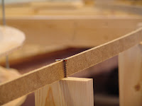
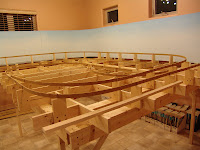
So what is a spline? First we cut 1/4 inch Masonite into 1 inch strips. The first strip is placed on the joists or on risers to follow the plan for the track of the main line. This strip is held in place by screws placed temporarily on either side on each joist or riser.

After the first strip is in place the main line of the railroad is defined. The next step is to glue additional strips of Masonite to  
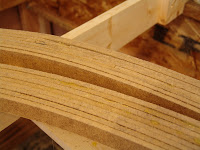
this guide strip. We mostly use hot glue to glue these splines together. The spline for this HO railroad required 8 splines to be glued together to form the roadbed that is 2 inches wide.

This process goes pretty fast but it does take a lot of strips and even more hot glue. If you have worked with hot glue you know that you have to work fast. We found that it is easier with a track crew (2 people), one to apply the glue and the other to immediately position and hold the spline in place. It is important to keep the top edges of the splines as level as possible during this gluing process.

The track crew found that when there is a turnout that the roadbed must accommodate this by allowing a spline to branch from the main spline. The crew found that gluing a small triangle to the first spline at the place of the turnout facilitated keeping the angle of the branching roadbed correct. The triangles were cut to accommodate the angle of the turnout. Most of the turnouts from the mainline on the Ascape Tennsion and Sulphur Gulch are #6 turnouts meaning that the branch line diverges 1 unit for every 6 unites of length. Again much more abrupt than the prototype but more practical for a model.

Where there are parallel tracks such as for a passing siding the crew found that it was more efficient to place a 1x2 between the splines as long as the parallel tracks were straight.

Once the splines have been glued it is critical that the top of the roadbed is level. We don't want the trains to lean from side to side as they proceed along the track. A very small difference in height on one side of the roadbed can made a noticeable difference at the top of a railroad car as it moves over the track. It is inevitable that one or more splines slips up a fraction of an inch as it is glued in place. To level the roadbed the track crew found that a small belt sander was the tool of choice. The top of the roadbed is sanded until it is smooth and also to be sure that it is level.

With the spline roadbed in place it will be time to move to large flat areas where spline roadbed is not practical. This includes the staging area, the yard at Ascape, Park City, and Coalville. We are still working on the spline but come back soon for a description of the next phase.
 

Dave Merrill

Reply 0
ACR_Forever

levelling comments

1) we use an electric planer to smooth the spline tops.  The planer has a bubble level insert glued to the nose.  So the operator of the plane just keeps the bubble within the lines.

2) we use cork on top of the spline, for noise abatement.  Any remaining wobble can be sanded out of the cork.  IF we remember...

Blair

Reply 0
mdavidmerrill

Leveling comments

I'm sure the planer would have saved me some headaches from failing to get the roadbed perfectly level.  We tend to use what we have in my case an inexpensive belt sander, which was somewhat less than perfect.  And yes we also top the spline with cork as will be shown in future posts.  Thanks for your comment

Dave Merrill

Reply 0
ACR_Forever

I have a belt sander too, but

I won't use it.  There's enough dust in my basement.  Don't need more.  I find the planer shavings/chips are a lot less dust prone.  On my planer, I use the bubble piece from a level that fell apart when I dropped it; I just hot glued it to the front of the planer in a level position.  Works great.  I hand-sand the cork, and vacuum up the mess immediately.

Joe Fugate has mentioned in another thread the use of 45 or 60 degree topped outside edge splines.  Sort of mimics the cork edge.  When you look at the real railroad's roadbeds, they often have a dual shoulder - the outer one is subroadbed fill, tapered around 30 degrees to the horizontal; up closer to the rails, the ballast also has a tapered shoulder.  So with a tapered outside spline, and the cork shoulder, there's some hope in my mind that we can approximate a prototypical appearance.  Since I've not tried the bevelled spline yet, time will tell.


Reply 0
mdavidmerrill

Sanding Spline Roadbed

Hadn't thought of a beveled edge on the spline, a bit too late for my railroad now.  

I also tried another trick that works pretty good.  You will find in a subsequent post that I use cheese cloth over a cardboard armature to form my scenery (you'll see this later if you keep reading this blog.)  I experimented with laying the cheese cloth across the spline roadbed and then mounting the cork on top of the cheese cloth.  This very nicely attaches the cheese cloth to the spline.  More later.

Dave Merrill

Reply 0
Howarg01

Spline roadbed on grade

You mention using a level on the planer to get a smooth flat surface, but what about grades?  I am planning a mountain railroad with 1.5% to 2% grades and don't see how the splice roadbed can handle that situation.  Obviously one could tilt the splice to the desired grade, but what about transitioning into the grade?  Nothing I have read regarding spline roadbed talks about how to construct transition grades.  Perhaps use short sections of plywood for the transition?

Reply 0
ACR_Forever

Just the opposite

Howarg01

The level is used to keep the planer horizontal from left to right; it isn't used for keeping the long axis of the plane level.  That axis is free to follow the vertical undulations of the spline.

Regarding transitions, I prefer to use the spline for that.  Using short plywood sections would introduce a step change, which is really unwanted. 

The spline is actually more useful for those vertical grades.  Although the main flex in a single piece is across the thin section, there is also quite a bit of flex across the thick section; in extreme cases, if we need more, I can cut the 1" down to 3/4", or even less, though I haven't had to so far.  Once you laminate 6 to 8 pieces of this, even the 1/2" will still be more than adequate for 24" spans, but will more easily form to the vertical curve desired.  

Consider the following:

We have yard A and yard B, both level, and 4" of rise from A to B.  We have 25' of single track subroadbed to create from A to B using spline.  That's nominally a 300" run for 4" rise, or 1.333% average.  I'm quite happy if the midpoint of that run is around the 2% max for my RR.  So I find roughly that midpoint, and set a riser so that the top of the spline at that point will be 2" above yard A.  We start the spline with two 8' pieces cut into the ply at A, and two cut into the ply at B.  When we glue these, we make sure the top of the spline is actually level with the ply, not angled down or up, at least for the first 1'.  We now have two unconnected spline runs pointing towards each other, with about 9' between them.  If you play with these a bit, you'll find you can quite easily form them into a transition to the grade you want, in a reasonable length, and the spline won't let you create a "step change".  The trick now is to connect them with the next length of spline, taking care to ensure that the continuous run thus formed actually lies across the top of the riser that sets it's midpoint elevation.  We did this with temporary spring clamps holding everything together until we had the pieces cut to the proper lengths.  Once we have that center 2-layer core in place, add risers where ever it seems necessary.  Do a final crosscheck of elevations, then start gluing that 2-layer core.  Check it again when done, then add laminations to suit.

We did a 0% - 3% - 0% stretch about 25' long in February, and it turned out quite well, other than a couple of undulations where I didn't get the planing quite right.  Planing the transitions takes a bit of practice, as for the concave one at the bottom of the grade you need to set your planer blade to cut deep, and pay attention to where you're on the grade or on the plywood, while planing the convex one at the top of the grade needs a gentle touch to feather it out, but it's quite controllable.  

Blair


Reply 0
mdavidmerrill

Just the opposite

Blair 

Thank you for your very good discussion of how to use spline roadbed for transitions to grades.  On the ATSGRR we kept yards and industrial areas flat (horizontal) but then as the main line leaves these areas the grade increases to 3% in some areas and then  back to level for the next industrial or siding area.  The spline has enough give to form very smooth transitions from level to a grade.  As discussed by Blair the secret is to extend long pieces of spline across the transition from level to the grade so it forms a natural transition.  If a joint is right at the point where the grade begins you might get a sudden jump which often happens when you use cookie cutter plywood for roadbed.  You'll see more detail in subsequent posts.  I maintain that spline is a way to form natural transitions into curves and into grades that are smooth and gradual. 

Thanks the discussion.

Dave

Dave Merrill

Reply 0
ACR_Forever

Dave

You're more than welcome.  I posted it because I half expected someone would chime in with "that's good, but it's so much easier to do it this way", and that's good too; as a lone wolf modeler, I develop techniques on the fly and move on, not stopping to consider whether there are even better solutions. 

This tang method works for me, but I do recognize that if one isn't careful, one can embed a lot of levering force on the glue joint, which is bound to fail someday.  


Blair

Reply 0
Reply