Craig Townsend
About 4 years ago I started my first major scratch building rolling stock project. Four years later, I'm still not done, but I'm making faster progress than before. A little background in the model, and the prototype to follow in the next post to keep this one on the short side. I have been in large scale 1/29 scale, G Guage for some 15 plus years, but I never really got serious about the scratchbuilding rolling stock (I have a huge scratch built feed mill I'm working on too; 7'x 6'x 4') until this project. It has been a fun learning experience and has really driven my modeling skills up and I have sought out new techniques and methods I would not have in the first place. Craig


BN 8th Sub Blog
Facebook group
fb://group/424898032713171?ref=share


Reply 0
Craig Townsend

Prototype History of GN Snow Dozer

The Great Northern in later part of the 19th Century, decided that they need to invest in snow removal equipment. The typical Russel, and Rotary snow plow had been used by the GN, but GN officials decided to create a specially built, snow specific plow. Thus, the job was given to the St. Cloud shops to build one of the first designs of the GN home designed/built plows, that GN loving called Snow Dozers.

These first Snow Dozers, were wood framed, boxy looking plows that combined the best of the best of snow fighting equipment into one package. The Dozers had a series of front plows, larger expandable side drag wings, and even a flanger. This all around piece of equipment was an ugly duckly that only GN fan could love.

"


But sadly the bruising and beating up that these Dozers took while plowing snow was just to much for the wood framed units. So GN went back to the St. Cloud Shops and had them build a new series of Dozers, this time with a steel frame.

The steel framed models still resembled their original wooden brethren, and proved to stand up to just a little bit more abuse than the wood frame versions. Over the years GN would have the St. Cloud shops build yet another series of Dozers for snow removal. Some of the versions looked a little boxier, while others  more streamlined, while others had flangers removed each version of the Snow Dozer that came out of the St Cloud Shops still had one and only purpose in life; get shoved by a locomotive or two a high speeds to clear snow from the mainline to ensure that traffic would continue to get through.

If a Snow Dozer couldn't break through the drifts than a Rotary would have to be called out. But more often than not, the Snow Dozers proved their usefulness, and GN ordered more to build up the aging fleet. GN placed it's last order to the St. Cloud shops around 1965, and in December of 1966 the shop forces began pushing out the latest, all steel, welded Snow Dozers. Numbered X7303 to X7306, where the last of the GN Snow Dozers, with the newly formed Burlington Northern getting four more additional dozers number BN 972500-972504. Weighing between 105,300 lbs, and 112,000 lbs these were also the heaviest Dozers yet, while stretching 15' over the top of the railhead, and having a pulling face of 49' 3" these Dozers would last well past their expected lifetime, with many reaching to ownership under the BNSF.

SaveCraig

Reply 0
Craig Townsend

Choosing Prototype to Model

Having been a Burlington Northern fan, and modeler most my modeling life, I instantly feel in love with the ugly duckly of the Snow Dozers when I first read a book by Martin Burwash, called “The Cascade Adventure” about BN’s struggle to get freight over Steven’s Pass in the wintertime. Burwash’s black and white photo’s brought alive the power of man and machine over “ Old Man Winter”.

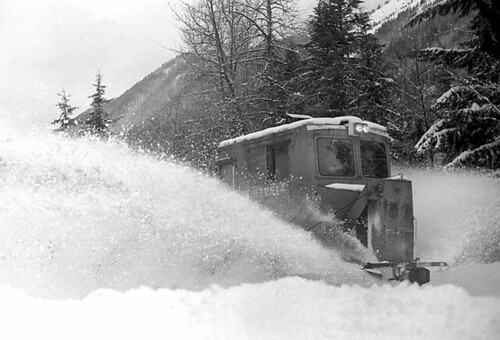
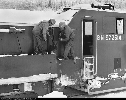
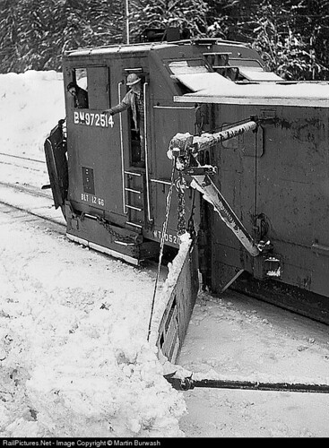
Martin Burwash Photos

Around the same time, I transitioned from HO scale to G gauge, and was introduced to the fun of operations. The weekly Friday night gang, religiously meet every Friday afternoon at a layout in the suburbs of Seattle. The gang meet and ran trains in sunshine, rain, sleet and even snow. The prospect of running a working snow plow came into my mind, and I began to dream of the day that I could build a working version of the Snow Dozer that I feel in love with. Fast forward, 10 years, and I began building my first outdoor garden railroad. That first winter, I equipped my GP9 with a hand built brass locomotive plow and plowed the few inches of snow that fell.

That next summer, I began thinking more seriously about building a Snow Dozer. I searched and searched the internet for information about GN Snow Dozers, each time coming up empty. Finally, I found a thread by a N scale modeler who built a non-working version. After a couple of email exchanges back and forth I was given copy of a hand drawing of BN snow dozer that the original author had used to build in N scale.

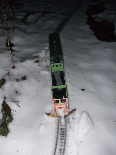
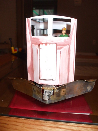
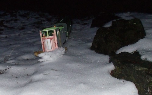
I quickly grabbed some styrene and started building what I thought would be the perfect working model of the Snow Dozer. By the time wintertime struck I had finished a rough model of a Snow Dozer; a bare frame stuffed with 2 large pieces of lead weight for traction, and a hastily built front brass plow. A few inches of snow fell that winter in the Seattle area, and I tested out the plow. It worked great!


That first plow triggered a quest to find even more information about GN Snow Dozers, and to build a more accurate model. By this time, I was married and was attending graduate school, so not much actual modeling was happening, but I used any available time, and newly acquired research skills to scour the internet for even more information. I found a few scraps of information here and there, but nothing that was more accurate than the original HO scale drawing that I received. Around this same time frame, I began seriously considering making a trip to St. Paul, Minn. to visit the Minnesota Historical Society library to do some in-depth research on a Northern Pacific proposal and my M.A. thesis. As, the possibility of making a trip to the MNHS archives, I began to wonder if the GN archives held on the same site would have any drawings on GN Snow Dozers.

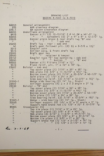
As luck would have it, I managed to carve out some archive time to search for GN Snow Dozer drawings. After searching through box after box, and not finding anything other than Authorizations For Expenditures (AFE), I finally found a box that had a complete list of each drawing number for the entire construction one version of the Snow Dozer. This four page document listed each and every drawing number I would need to correctly build a version of the Snow Dozer. Because time was running out in my archives search, I quickly requested another box that I thought would contain all of the drawings I needed.

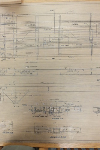
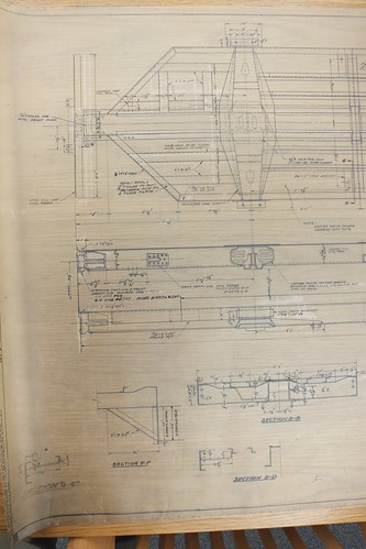
I opened this latest box, and before me were multiple original drawings (measuring 30” x 60” or more) that I would need to build a Snow Dozer. Quickly without much thought, I snaped a series of photos of each drawing. It wasn’t until I got back home at the end of the week, that I actually looked what I had found. In my haste, I missed quite a few other drawings that I now need, but these first few drawings started me on the project I’m currently on.


The drawings included; a full underframe, full body, general arrangement and a few detailed drawings of the front wing plow, along with some other assorted drawings. These drawing would prove to be a gold mine as eventually I would find out that they were of the exact prototype I was trying to model; BN 972514, or GN X7303, one of the last versions of the Snow Dozer to come out of the St. Cloud shops and stationed in the same territory that I was modeling.

I hope this is enough to wet everyone's appetite for this build...

Craig

Reply 0
Craig Townsend

Building the underframe

So after I found the original GN drawings, I knew I had to rebuild the Snow Dozer to more correct scaled model. Initially, I was planning on building it out of brass for actual plow service, but I quickly realized that the CFO would have approved the required budget.

At this time, I had graduated graduate school and was looking for a full time job.So I settled for a styrene model that will not be a functioning model but rather a display piece. I still plan to build a brass version when I get done with the styrene version and set it up with working servos. As I looked at the under frame drawing, I began a shopping list of styrene of assorted Z, C, and H channels, along with various strip stock. The plan was to build the entire model to as close of scale sized pieces as possible. After 2 failed attempts at the underframe, I finally succeeded. The construction of the underframe took about a year as I didn't have a lot of time dedicated to modeling. But I plugged along and keep building. Crossbearings were constructed out of .010" stock, per the drawings, and mounted to the centersill which was a piece of square tubing cut into a channel. At one point I thought the under frame wouldn't be strong enough to support the rest of the dozer, but as I kept building it got stronger.


Craig

Save

Reply 0
batey_1020

I really enjoy watching

I really enjoy watching people build rolling stock in styrene. I haven't done for many years now but some time soon i should tackle another scratch build.

Please keep posting. Looks like an awesome start.

Multi Deck Ho Logging Railway in the North West

https://owenpass.blogspot.com/

Reply 0
Craig Townsend

Thanks. It's been a long

Thanks. It's been a long build so far and I would only say that I'm halfway done. But with the amount of modeling time I can actually squeeze out of each day, I think I've gotten pretty far. It doesn't help that I tend to build each part 2 or 3 times until I am satisfied that it is correct. Hopefully I will post some more on this build later today. Craig
Reply 0
Craig Townsend

Brake Piping and Airlines

One of the neat features about the GN design for these Snow Dozers, was that everything was run off air pressure instead of hydraulics. This required not only the regular airlines, but also an auxiliary line to charge, and run the various appliances. The auxiliary lines runs off main reservoir pressure, and has to holding tanks. In my initial search for drawings I was able to find drawings that showed all of the brake piping arrangements in detail on the underframe. I later found out that another entire set of drawings cover the internal piping to from the control stands to each of the pneumatic cylinders, and holding tanks. I'm debating about modeling these lines, as I believe they are hidden in the carbody frame.

Thanks to a fellow large scale modeler who had designed the AB brake components for 3D printing, I was able to quickly progress through this stage to get the model ready for display at the Pacific Northwest Prototype Modelers meet in 2016.

Using his designs, I was able to make a RTV mold, and cast my own copies in resin. One modification I made to one of the castings was to drill out the brake piston in preparation for styrene plug, as at the time I wasn't sure if I wanted to build the model with the brakes applied or released. Through the use of various sized brass tubing, and wire, I was able to plumb most of the airlines. The brake system isn't 100% complete, but the basic structures are present.

It was also during this time that I began to sketch out designs for the framing of the Dozer. I will cover that in the next posting.

Craig

Reply 0
Craig Townsend

Carbody construction

After I completed the underframe, I started work on building up the Car body Originally, I was going to construct it out of 3" angle covered by thin sheet stock, much like the prototype drawings. By a test sample showed that this method had a lot of problems with the strength of the construction, and the mass amounts of angle that I would need to buy. So instead I took .040" and .060" sheet stock to make .100" stock th a was pretty close to the required 3" thick design. Becuase I was in a hurry at this stage, I made a huge mistake that I didn't catch tell much later. When I glued each side on I left a .010" gap between the under frame and the carbody sides. This has resulted in hours of putty and sanding to correct. When I realized this mistake I couldn't pull off the car body sides without ruining the entire underframe. So I marched onward. I'm currently still sanding and priming the sides. One side is about 90% complete, while the other is about 60% done. The reason I have to smooth everything out at this stage is because the side Drag wing builds off the car body. There would be no way to smooth it out once that detail was on. Not a very interesting post, but its one of those details that make you go ouch. When the sides are done, I will post some pictures. While working on this, I also started working on what is called the front cage. Next post I will describe what and how I bult that. Craig
Reply 0
Craig Townsend

Front Cage

One of the defining features of the GN Snow Dozer is the front plow arrangement. This front plow area is known in the GN drawings as the "Front Cage". As I was building this part, I began to understand why GN named this. This part is one of the critical parts of the build that would begin to define that ugly look. Again, I was able to find the drawing for this series of Dozer, and I set to work constructing it.

I started with C channel of various sizes, and pieces of .020" stock to build this part up following the drawings as best as i could. Some final details are still needed, but the major assembly is finished. This entire cage is lifted and lowered by a pneumatic cylinder inside the dozer. This allows the front blades to drop down to the railhead.

< imhttps://c1.staticflickr.com/4/3693/32955190951_358bcaf6a6_c.jpg" />

And a not so great photo of the front cage sitting in place on the Dozer.

It's finally starting to look like something now...

Craig


Reply 0
Eric Warhol ewarhol

Great Job

Looking great Craig! Keep updating us with progress, fun to watch progress on a good old fashion scratch build model. 

Eric Warhol

Reply 0
Craig Townsend

3D Parts, design and printing

I haven't posted much on this build lately as what I was/am doing is kind of boring, and the pictures wouldn't really show much progress. For the past few weeks I've been busy designing and redesigning parts to be 3D printed. These parts are the assorted hardware to make the side drag wings work. I started out trying to make these by hand, but it was way too close of tolerances that I didn't have the tools or skills to do. So I turned to 3D printing. I had previously used Sketchup for some other modeling woek, so I began working on these parts. In the end, I was able to print off a few parts for casting, and a few stand alone parts. According to Shapeways they are in production mode, and I should have them by the 20th. Meanwhile, the model is getting primed and sanded in preparation for these parts as the exterior walls wont be very accessible for priming and sanding once these parts are attached. Stay tuned for more details to come. Craig
Reply 0
mrtrenes

Fantastic!!!

DSCN1144.JPG I am building my own dozer in HO scale!! 

Reply 0
Craig Townsend

Those plans look like the

Those plans look like the original ones I found. I've got some original GN plans if tour interested. Hope your enjoying the build in HO scale! Craig
Reply 0
Craig Townsend

Scratchbuilding isn't cheap!

Oops this was an expensive mistake.... I opened up my parts of Shapeways that I got today in the mail, and as I was looking at them a few of them looked a bit off. Nobody said that scratch building was cheap, rIight?


Come to realize that quite a few parts had been reduced to the incorrect size. For example, one part that was supposed to be a scale 12" wide came out to 9" wide. Another part that was only supposed to be 6" wide ended up 16" wide. The lesson is double check your measurements before hitting submit to the 3D printer.


I think I can manage to salvage a few, but I might contact Shapeways anyway as two of the major parts came bent. I'm not sure if this was in the shipping or in the cleaning process. But when a flat part doesn't lay flat something isn't right. Plus the parts met all of Shapeways minimum requirements on sizing.


I'm also going to redraw some of the boom parts to make the boom piece as one solid piece. I had created it as 4 separate parts that I would connect with a piece of styrene tubing, but looking at the size and shape of the parts it will be easier just to order them as one solid piece.


I think I might also try and design a bending jig or maybe even a piece of roof section to solve my earlier problem about trying to figure out a jig or roof construction as well. Time will tell.

Craig

Reply 0
Craig Townsend

3D Parts Finally Done!

I've had a huge learning curve trying to learn how to design and print parts from Shapeways. A few screwups on my end and a screwup on Shapeways end, but I think I now have most of the parts ready to print to finish the exterior of the Snow Dozer. Was it 'faster' to design and print in 3D verses using stryene? Not really. In fact I think that I would have spent just as much time doing this the traditional route.

Praise for Shapeways customer service. One of the original parts that I had ordered came with a warp. I contacted Shapeways and they reprinted the warped parts for free. So I tweaked the design a bit, and double checked the scaling and reordered. I also reordered some of the other parts that I had scaled wrong. Finally, today I figured out how to draw a cross section of the roof, so now I've got that on order. A 1' scale section of the roof should be enough to cast copies from and glue together to get the correct length. Should be a bit cheaper than ordering the whole roof from Shapeways.

All of these parts are due to me around April 10th, so that gives me a little under 19 days to get the exterior of the Dozer done for the RPM meet. So, I have 8 days right now to get the body of the Snow Dozer ready for these parts.

Craig

Reply 0
Craig Townsend

Drag Wing and Drag Wing Support Boom Construction

As I mentioned in the above post, I turned to 3D printing to not only design but also print some parts. These parts are in the 3" to 6" range and would have been quite hard to make. However, these parts are the critical parts that allow the drag wing to rotate on both the X and Y axis. In my quest for drawings, I was unable to find the detailed drawings for these parts, but I had enough information from other sources that allowed me to create a drawing. The drag wing itself, is constructed of sheet steel over a substructure of H beams. The drag wing is raised and lowered by a system of pneumatic cylinders and a pulley and cable system. It was this system that I really wanted to replicate on the model. I ended up drawing 8" and 10" pulleys to run the .018" stranded cable though. On the prototype this is a 5/8" cable. All of the above 3D printed parts relate to the drag wing pulley system, or the drag wing support boom. I discovered that by nesting the 3D printed parts together I was able to save about $15 on the cost of the print. When I get the boom and drag wings assembled, I will update the thread with pictures.The plan currently is to use a combination of these printed parts, brass rod, and styrene rod to complete the construction of the booms. Craig
Reply 0
Craig Townsend

1 step forward, 3 steps backward

So I haven't forgotten about this build, but I've taken 3 steps back, 1 step forward kind of progress. For the past couple of months I have been working on the drag wing for the Dozer. On the prototype this is a 21' x 4' slab of sheet metal framed by 5" H beams. Version 1 was tried by building up styrene H beams. I quickly found out that the extruded H beams don't have a full right angle connecting the sides of the H beam. Instead it has a ever so slight contour from the extrusion process. This means that when trying to tie two H beams together at a right angle, you end up having to file part of the extrusion away. This lead me to version 2. Version 2. Make H beams from .030 x .172 strip stock. Than glue together, and over lap with sheet stock to replicate the slab. Version 2 turned out fairly well on the first one, but construction of the second resulted in the styrene warping into a tight curve that proved to messy to deal with. This lead to version 3.. Version 3 was going to be the "final" solution. 3D print the H beams as one solid piece, and than laminate with a sheet of styrene. A few minutes designing, and I sent it off to Shapeways for a print. The Shapeways print came out good, but because it was such a flat piece, it had a curve due to the manufacturing process. A quick dip into boiling water fixed said warp. I proceeded to laminate a piece of .015" sheet stock on the 3D print, and left for vacation, hoping to finish the final assembly. Nope! The styrene rewarped the H beams to an even tighter curve. Another dip in boiling water to fix the curve. Nope, still there. Version 4. Place an order for 5/32 brass H beams and use my resistance soldering unit to build up the parts. Version 5? Hopefullly the brass version will work and I won't have to make version 5!
Reply 0
Craig Townsend

Progress Update

So I have been plugging along with this model over the last few weeks. I have almost completed the details on one side of the dozer including the drag wing, drag wing support crane, drag wing piston, and all of the associated handrails, grab irons and ladders. I ended using a HO mu cable receptacle to represent a plug in that the prototype had on the side. The grab irons are all 1/32 brass rod bent to fit, and then secured. Years ago, someone sent me some brass etchings that replicate the NBW detail for the grab irons. Those are than glued next to the grab iron and a HO scale NBW is added to complete the detail.

I still have to make a couple of brass ladders for the main door, along with a stirrup for the back porch. Than it's cutting out slide glass for the windows, and making covers as on the prototype. It's hard trying to keep all of the sub assemblies from hitting the paint shop!

0946a(1).jpg 

21171648.jpg 

0_52_Pro.jpg 

On my other thread about chipping fluid and hairspray., I'm experimenting with trying to replicate the rusting patterns on the prototype. I'm hoping to finish the backside details, and the engineer side details over the next couple of weeks before I go back to teaching in September.

Craig

Reply 0
pschmidt700

Looks great!

Everything looks crisp and well put-together.
Reply 0
Craig Townsend

Primer is my friend!

Primer covers a multitude of mistakes... Craig
Reply 0
Craig Townsend

Summer 2017 Update

As a teacher one would expect that I could get more modeling done during the summer, but life has a funny way of pushing aside modeling for fun summer activities like camping, and doing yard work.

Now that school is back in session, I should be able to find more time on modeling as I use it to decompress during the week after teaching 180 high school students!

Here's some updated progress photos. I started with a USA Trains 50' boxcar roofwalk, and cut it down to make the end platform and the side ladders that are used to access the interior of the dozer.

0_18_Pro.jpg 

This is the end result.

8_33_Pro.jpg 

9_45_Pro.jpg 

The diamond tread was found in my scrap box from a long lost project. I recall ordering the diamond tread from PSME years ago to use as platform steps for a grain elevator. One side almost done, with the exception of cutting slide glass for the windows, and making window covers. The plan is once I get all four sides done, and primed one last time, Archer rivet and weld decals will be added for the final touch. The roof will be next, and I hope to have some roof sections laser cut by another large scale modeler. Will try to post more updates and a better build log description later this weekend.

Craig

Reply 0
Deemiorgos

Incredible detail and such

Incredible detail and such nice work, Craig. So look forward to more posts.

Reply 0
Craig Townsend

Almost ready for a big update

Thanks. Its been a fun build so far. Right now I'm in the process of cutting slide glass for the windows. When I get done with those, I think it will be time for a formal update and write-up. Here's a sneak peak, warts, messy putty and gap fillers.


1808b(1).jpg 

Reply 0
Deemiorgos

That's quite the close up

That's quite the close up shot so much so I can't tell what part of the car it is.

Slide glass must be very thin.

Reply 0
Craig Townsend

1mm thick slide glass

The slide glass is 1mm thick. I "think" I may have finally figured out a way to cut the slide glass. When I started it was about a 95% failure rate. Now its down to about 20%. The extreme closeup is of one of the back windows. Last night I was able to clean up around that window so it looks a little nicer. I want to get one side finished before I post a longer update. Craig
Reply 0
Reply