DKRickman

I actually got something done, instead of just talking about it!  Well, when I say done, I mean started...

With the arrival of the new TSC sound decoder, I needed a tender to put it in so that I could compare it to a Tsunami.  And since there's no point in doing a bunch of work installing a sound decoder and speaker in the wrong tender, that meant I needed to get off my duff and build a tender.  Since I now have enough locomotives to model every D&W steam loco from #19 up, and more importantly to model #s 20-24 (the main roster in the '40s) I really don't have much excuse.  Much research ensued..

Ken Rickman

Danville & Western HO modeler and web historian

http://southern-railway.railfan.net/dw/

Reply 1
DKRickman

Plan A: Sketchup

My first attempt was to use the various photos I have of the Danville & Western's locomotives to make a 3D model of them in Sketchup.  This is what I came up with:

DW_22_1.jpg 

DW_22_2.jpg 

DW_22_3.jpg 

Not bad, right?  That at least gave me something to work from for #s 22 & 23 anyway.  Unfortunately, the only dimensions I had to start with were those of the cab (and that was a guess) and the driver diameter.  Also, I don't have as many photos of the tenders behind the other locomotives, which meant that making accurate drawings of them was going to be harder.  I needed a better plan..

Ken Rickman

Danville & Western HO modeler and web historian

http://southern-railway.railfan.net/dw/

Reply 0
DKRickman

Plan B: Logic

I needed a better plan, and some sort of verification that I was on the right track with the drawings I'd already done.  Logic to the rescue!

I know the capacities of the 5 tenders in question.  #s 20&21 had 4500 gallon tanks, while #s 22-24 had 5000 gallon tanks.  I also felt safe in assuming that there were at most three tender designs.  #s 20&21 were siblings, built at the same time by the same builder, though one was a 4-6-0, the other a 2-8-0.  The builder's photos of both definitely seem to show identical tenders, right down to the number of rivets (yes, I counted them).  #s 22&23 were twin sisters, so logically they had the same tenders.  #24 was built a little later, and by a different builder, but the tender having the same capacity made me think that it would be similar if not identical.  The rivet patterns bore this out - similar, but not identical.  The overall size certainly seems to be the same, or at least very close.

So far so good.  I'm working under the assumption that there are two basic designs, with one of the larger tenders having the same size but a different internal structure and therefore different a rivet pattern - easy to deal with using rivet decals.  So it looks like two frames and two tanks will need to be designed, which is a significant improvement from the original 4 different designs.  But is that it?

Southern Railway had a major influence on the D&W.  The locomotives seem to have used standard Southern cabs.  The Baldwin orders repeatedly refer to "Sou. Ry. Std." for a number of minor details.  And it just so happens that I have quite a few drawings of Southern steam locomotives.  I wonder if any of them might have had similar tenders?  I went looking for tenders of similar age and capacity, and lo and behold, I found some.

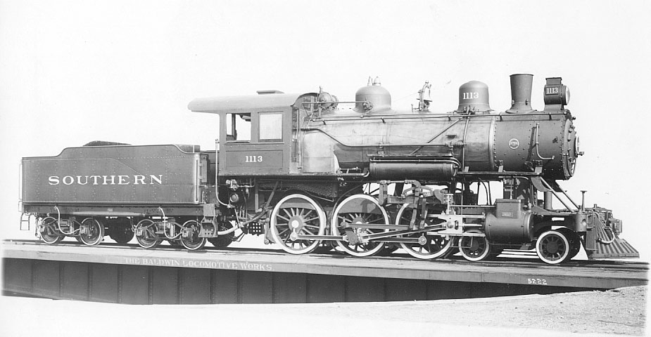
The 4500 gallon tender I found behind an 0-6-0 switcher.  Other than a different coal bunker and the lack of a vertical seam on the tank, it looks like a dead ringer.  I even found what looks like a Baldwin builder's photo that looks almost exactly like the builder's photos of #s 20&21:

And, I even have some really good drawings of that engine, thanks to an article in the March '91 Mainline Modeler, of which I have an electronic copy.  Fixing the coal bunker to suit my needs will be child's play, with accurate drawings of the frame in hand.

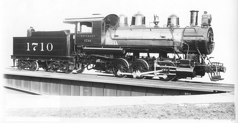
One down, one to go.  I managed to find a few Southern engines with 5000 gallon tenders as well.  Most of them were older, which didn't really help me much.  All of them had the older style horseshoe tanks, whereas my engines had the newer style tanks with the coal bunker coming all the way to the outside, and smaller water legs up front.  But there in the list of locomotives from 1929, was a reference to an engine built after 1900 with a 5000 gallon tender.  And when I looked for it, I found this:

Eureka!  The rivets match perfectly, the bunker has the same shape.  I'd be willing to bet that the tender behind #24 was a dead ringer for the one above.  And, while I don't have plans for that engine, I do at least have an elevation drawing which shows the bolster spacing and (most helpfully) tank length and width.  I'll have to extrapolate the frame dimensions, but that looks doable.

So now I have drawings.  The 4500 gallon tender will have a 12' bolster spacing, while the 5000 gallon tender will have a 12' 9" spacing.  The larger tank is about a foot longer and an inch wider.  Comparing the drawings of each tender, it looks like I can simply stretch the smaller one by 9" to get the larger one.  If that's not exactly what was done, it would certainly be within a few inches anyway, so that's what I'll do.

So now there's a critical question.  How does my Sketchup drawing (made without any dimensional information about the tenders) compare with my deductions based on Southern and Baldwin practice?  Well, I was off.  Way off.  But when I scaled my drawing down about 10%, it turns out that I was within a couple inches all around.  That's good enough for me.  It makes me think that at the very least my logic is not completely off, and that building tenders from the plans as described will yield reasonably accurate models.

Not bad for starting with a handful of photos and no drawings, huh?  Time to get started!

Ken Rickman

Danville & Western HO modeler and web historian

http://southern-railway.railfan.net/dw/

Reply 0
DKRickman

Take One: Brass

I like working in brass.  Especially for something like a small tender, it gives good weight.  I even have the materials on hand.  So, let's get to work.  I cut some floors out of .010" sheet, and a couple 1/8" square rods for the end beams.  That's where I stalled.  What's the best way to make the "C" channel frames?  How do I make the different thickness front and rear beams?  I can do it, but it's going to be a lot of work with a Dremel and a file, and it's going to be noisy.  This is starting to look less like fun.  As I'm rooting through my materials bin, looking for inspiration and that elusive perfectly shaped piece of brass, I noticed something.  while I don't have the right size material in brass, I do have it in styrene.  A .100" "I" beam is exactly the right size, according to the scale drawing I printed out.  not only that, but I have some .100" x .188" stock which would work for the end beams, and I even have grooved sheet which would make perfect 12" deck boards.

Hmmm...

Brass..

Styrene..

Darn, I wanted to show off 5 brass tender frames by the end of the night.  Oh well, styrene is easier to work and I can build a better model.  That's the point, isn't it?  Get it done, and do the best you can.  Time for a change of plans!

Ken Rickman

Danville & Western HO modeler and web historian

http://southern-railway.railfan.net/dw/

Reply 0
DKRickman

Take Two: Styrene

With all the preliminary stuff out of the way, and having spend the requisite time staring at the plans and my assembled bits of raw material, it was finally time to get to work.  I started by cut out out pieces of scribed styrene large enough for the decks.  In my case, that means 8' 6" wide, and roughly 22' 3" and 23' long.  I then cut a nice pile of "I" beams, again in two different lengths.  Finally, I cut 10 end beams.  Since .188" is way too thick for either the front or back beans on the tenders, I had to do something.  The back beams were easy - I cut notches in them so that the remaining portion would look like it was about a scale 6" thick.  The front needed to be tapered, so that the middle was thicker than the ends.  A sharp chisel took care of that.

Working on a sheet of glass, I assembled the frames upside down.  Once they were glued up, I added bolsters for the trucks, and fore-aft beams to mount the couplers and drawbars, all made out of the same .100" x .188" strip.  Since I had decided to make all of the frames identical, except for stretching three of them by 9", it was easy to measure all of them the same way, working from either end.

I'll be using two different trucks with these engines.  The ten wheelers (#s 20, 22, 23) will use Bachmann Spectrum trucks, since that's what the models will be built out of.  The consolidations (#s 21 & 24) will use MDC trucks, since that's what those models will be built from.  The two trucks are very close in appearance, but they have different bolster heights.  To determine what height I needed, I mounted a coupler (Accu-Mate Proto) on one of the frames, then started stacking various bits of scrap until the coupler was the right height.  For the Bachmann trucks, it turns out that I needed .100".  That's convenient.  The MDC trucks needed about .140", which was also easily managed with the styrene on hand.  So I cut squares of styrene and glued them in place.  when the glue cured, I measured for the proper screw hole locations and drilled them out.

Now, the TCS decoder instructions suggest that it would be a good idea to mount the decoder on a heat sink.  I know that the Micro-Tsunami also benefits from a heat sink.  Since I'm not sure what decoders I'll be using in all 5 of these engines, it would be nice if I could go ahead and design for a heat sink now, and avoid having to retrofit one later.  I also need some weight, since styrene frames are pretty light things.  What I came up with was to cut out the center portion of the deck, between the "I" beams and the bolsters.  I then carefully shaved away the top inside flange on the "I" beams, leaving a neat little pocket into which I could drop some flat steel weights.  I just happened to have some old freight car weights which, by some amazing stroke of luck, fit nearly perfectly between the beams.  A few minutes with a hack saw and a file, and I had 5 weights ready to glue into place.  conveniently, they're also slightly recessed below the deck, which means that I have room for more weight, or I can mount the decoders that much lower (and have that much more room for an enclosure).

The last piece of the puzzle (so far, at least) was figuring out how to actually mount the trucks.  I needed some kind of spacer, so that I could tighten the screws while still allowing the trucks to turn.  None of my styrene or brass tubing on hand fit the holes neatly, and I didn't feel like turning any down.  Then it hit me.  Bachmann provided me with the perfect part.  There is a little plastic piece which fits into the tender frame on the Spectrum 4-6-0, and which includes a round pin for the truck to turn on.  Perfect.  I trimmed it down so that it won't interfere with the tabs on the truck which hold the wipers in place, and them mounted it upside down from the bottom of the truck.  Job done.  I still need to sort out something for the MDC trucks, but that will come in time.

So, this is where I am tonight.  I have 5 tender frames, with weights.  One of them is sitting on trucks.  I could have all of them on trucks in a matter of minutes, and couplers would take only a few minutes more (since I drilled all of them for coupler boxes already).  Basically, I need to build some tender tanks now.

rs%20(1).JPG 

rs%20(2).JPG 

rs%20(3).JPG 

When I get around to building the tanks, I'll do all 5 at the same time.  However, since I only have 2 decoders and speakers, I'll only get two operational for the time being.  My plan is to put identical electrical connectors in all of these tenders, so that I can use one behind any of the 5 engines.  That should make testing as I build the 5 engines a little easier.

Ken Rickman

Danville & Western HO modeler and web historian

http://southern-railway.railfan.net/dw/

Reply 0
barr_ceo

Never forget there's another

Never forget there's another dimension you know, too, though the angle may not be the best. Four feet, eight and one half inches.

If you keep on doing this sort of scartchbuilding, you might want to invest in a good pair of proportional dividers and a couple of engineer's scales. (those triangle "ruler" things...   never draw with them, BTW...)

The dividers aren't cheap, even lower end ones, but they'll save you a multitude of migraines doing this kind of work!

http://www.micromark.com/Proportional-Divider,6494.html?sc=WGB&utm_source=GoogleBase&utm_medium=feed&utm_campaign=GoogleBase&gclid=CMb6oe-Ys7kCFcbm7Aod8DwAdw

Yes, those are the cheap ones...

You can jump into Photoshop or GIMP and take a picture like those on the turntable, then use some of the perspective tools to make the top and bottom "square" again, giving you a much better shot at getting accurate dimensions. That works best when you're close to being square-on to the object in the picture, but if you're desperate you can get some fair results even from a 3/4 view if the original picture is sharp enough.


Reply 0
dfandrews

The "thinking it through" process

Ken,

I really enjoyed reading about your thinking process for this project.  In the beginning I thought, 'what about similar tenders for other roads', then there you were, looking at the Southern.  It's sort of like going on a treasure hunt. 

I'll be following this closely (as I usually do when you post your projects).

Thanks.

Don - CEO, MOW super.

Rincon Pacific Railroad, 1960.  - Admin.offices in Ventura County

HO scale std. gauge - interchanges with SP; serves the regional agriculture and oil industries

DCC-NCE, Rasp PI 3 connected to CMRI, JMRI -  ABS searchlight signals

Reply 0
Bernd

Will be following along

Ken,

Great write up on doing the research. Also great start on getting a fleet of engines built.

Quote:

What's the best way to make the "C" channel frames?

Ask a guy with a milling machine if he could make some.

Bernd

New York, Vermont & Northern Rwy. - Route of the Black Diamonds - NCSWIC

Reply 0
DKRickman

Glad you like

barr_ceo,

If you look closely at my Sketchup images, you'll see that I've drawn lines to indicate the rails as well.  Unfortunately, the angle of the photos made using that dimension as a primary reference pretty much impossible.  I did however use it as a double check.

Photoshop and GIMP are excellent tools for the purpose, and I love the perspective correction tools, but they are limited.  They can give a reasonably square image, but that do not give you accurate proportion (length to height) information.  Once I learned to use Sketchup to work on photos like this, and especially once I learned how to work with multiple photos (all three Sketchup images above are views of the same drawing), I found that it is actually a much more powerful tool for some purposes.

So far, since almost all of my data is digital, I have not felt the need for physical drafting and measuring tools.  They would be nice, but I've so far been able to do without, or work around the need for them.

Don, Bernd,

I'm glad you like the description of the process.  I thought it would be more interesting than just "Here are the plans, and here are the models so far."  There's a lot that goes into getting to the cutting styrene stage, and a lot of blind (or half blind) alleys have to be explored.

Next up, deciding whether to make the tender tanks out of brass or styrene.  It may depend on how much material I have on hand!

Ken Rickman

Danville & Western HO modeler and web historian

http://southern-railway.railfan.net/dw/

Reply 0
OhioMike

Measureing a dimension with a

Measureing a dimension with a "proportional divider" doesnt need to be that expensive....a school supplies style or better compass will do the same thing...i got cheap more than once!

Mike

Reply 0
dmbott

As usual, you're miles ahead of me

I'm just not good at cutting square joints, so I have decided to "make do" with commercially available tenders.  Now you had to go make it look so much easier to scratch build than I thought.

You'll have a full Dick & Willie way before I get my 4x8 A&Y complete.  Please tell me you don't have two kids in grade school.  I keep trying to use that as an excuse.  sigh.

Following along mostly happily,

Dave

__________________________

Dave Bott​ models the A&Y in HO

Reply 0
barr_ceo

Measureing a dimension with a

Quote:

Measureing a dimension with a "proportional divider" doesnt need to be that expensive....a school supplies style or better compass will do the same thing...i got cheap more than once!

A proportional divider (see previous pic) isn't JUST for getting dimensions off a drawing or photo... it has TWO ends, and a movable pivot. You can adjust the proportions so that you're not just getting the dimension, you're scaling it at the same time.

Try THAT with a compass.

Reply 0
DKRickman

Easy as 3.14159....

Quote:

I'm just not good at cutting square joints, so I have decided to "make do" with commercially available tenders.  Now you had to go make it look so much easier to scratch build than I thought.

The trick is generally to plan the work so that your cuts don't have to be perfectly square!  For example, I doubt any of those large styrene chunks has a perfectly square end.  But since I glued them to a sheet which I know was cut nice and square (easy to do when you start with a square sheet), I know that all the joints will end up square as well.  Any minor gaps are simply hidden, or they'll be covered up or filled later.  For that reason, I try to make sure to always leave a square cut on my supply of sheet styrene.  If I were to leave an end a few degrees off or square, it could mess up many future projects, so I'd rather waste a little if I have to and leave myself a clean edge for the future.

And honestly, scratch building is easy.  The hard part is figuring out how to do it, and more importantly what to do.  That's a big part of the reason why I shared the story of research and development - that's the really hard part in most cases.

Quote:

Please tell me you don't have two kids in grade school.  I keep trying to use that as an excuse.  sigh.

And here I was thinking I've been moving too slowly. And you'll be happy to hear that I have no kids, grade school or otherwise.


Ken Rickman

Danville & Western HO modeler and web historian

http://southern-railway.railfan.net/dw/

Reply 0
DKRickman

Getting tanked, part 1

With the frames under control (though not finished) it's time to get to work on the tanks.  I started by making a quick drawing in CAD, just showing the top view of the tanks.  I had to figure out how long the wrapper would need to be, and I needed the drawing anyway (you'll see why in a bit).  With that done, I drew a long rectangle for the wrapper, and raised the coal bunker sides at the proper locations.  I also marked where the curves would end as the wrapper goes around the tank.  I then made sure to remove .01" (actually, .871", since I was working with scale dimensions) from the perimeter of the plan, to allow for the thickness of the wrapper.  Anal, perhaps, but it's so easy, there's no excuse not to do it.

Bear in mind that I still hadn't figured out exactly how I was going to build these things at this point.  I just knew that it was easy to draw all this stuff, and it would probably come in handy later.

I then copied my drawings so that I had ten plans and 5 wrappers, making sure to have enough of the two different sizes, and printed them out in HO scale.  If I had been thinking, I could have saved myself a step by grouping the wrappers more tightly.  As it was, I had to cut the drawings out and reassemble them by hand.  Oh well..

I glued my drawings onto a couple styrene sheets.  .040" for the plans (to become the tops and bottoms of the tanks) and .010" for the wrappers.  I used plain old rubber cement, making sure to apply it evenly and let it dry completely before gluing the paper to plastic.  This is what it looked like:

rs%20(4).JPG 

Like I said, it would have been a lot neater if I had drawn the wrappers nestled together properly.  I could have saved myself a little time cutting, and wasted a little bit less material.  Live and learn.  I did at least print the outlines as shown, and I was lucky enough to have them just fit across the sheet of styrene.

I used a VERY SHARP (as in, freshly sharpened to a fine point, just for this job) knife to cut the wrappers out.  I then simply cut the outlines out as rectangles, using the old score and snap method.  For the moment, I'm leaving the paper on the pieces.  with the wrappers cut out, I wrote the engine numbers on them (to make it easy to keep track of which was which) and then formed the bends around the shaft of a small screwdriver.  For the tight (4" radius) bends at the rear of the smaller tenders, Rather than working around a form I simply carefully folded the styrene and paper in half.  How tight the crease is pinched determines the radius it wants to take.

I also took a couple scraps, with paper still in place, and did some tests.  One I folded completely in half, making the crease as sharp as I could.  I wanted to test how tight a curve it could take without breaking, and it held up beautifully.  I suspect that the paper on the outside of the crease serves as reinforcement.  I even liberally applied MEK to the inside, something which has in the past caused sharp bends like that to break along the weak point.  No problem.  On the other scrap, I intentionally got MEK on the paper and the rubber cement.  I wanted to know what would happen if I glued pieces together with the paper still in place.  Once the MEK dried completely, I peeled the paper off, and found that the surface was still quite smooth, but the rubber cement did not rub away as cleanly where the MEK had been.  So it's probably best to remove the paper if there's any risk of MEK getting to it.

Cutting out and bending the wrappers went remarkably quickly, and much better than I had expected.  Having the ends of the curves marked helped immensely, since I could see where they needed to be bent.  By holding the wrapper in front of a strong light, I could see the screwdriver shaft through it and ensure that it was square before I started rolling.  Here's what I had after just a few minutes of work:

rs%20(5).JPG 


Ken Rickman

Danville & Western HO modeler and web historian

http://southern-railway.railfan.net/dw/

Reply 0
DKRickman

Getting tanked, part deux

Now it's time for a little design on the fly.  I have already redesigned part of this in my head, but as I'm at work right now, the rebuilding will have to wait for a few days.

The basic plan is to use two .040" outlines as the top and bottom of each tank, and also to let them be the formers to which the wrappers are glued.  The result should be a nice styrene box which can serve as both tender tank and speaker enclosure.  First things first, I took two of the larger pieces and cut the recess out of one side, where the front (coal boards and water legs) will go.  I then rounded the corners with a file, using the paper as a guide to make sure I got the right radius.  A quick check with one of the wrappers showed that the fit was remarkably good - especially for having cut, filed, and bent things by eye.

I started with the tender for #24, since that's the one I've decided is getting the B'mann Tsunami, and because you have to start somewhere.  I measured the diameter of the speaker that came with the model, and cut a round hole in the top piece to match.  I decided to locate the hole as far back as possible (actually, close to perfectly centered in the tank), the theory being that it would give better acoustics inside the enclosure, and it will allow me to model the coal load being lower in front if I want to.

With that done, I measured the decoder circuit board, and cut a rectangular hole to match in the bottom piece.  In one of those rare strokes of luck, the top surface of the circuit board sits perfectly flush with the top of the bottom sheet because the steel weight over which the decoder will fit is recessed by the perfect amount.  That will make mounting the decoder super simple.

The final step which I got done before being called for work was to make and glue in a pair of spacers to hold the top and bottom apart at the right distance.  I carefully measured and figured out how much of the wrapper I wanted to protrude above the top sheet, and how high the spacers needed to be, and then cut them out.  I glued them in place, glued the top sheet on (using a square to make sure the top and bottom were properly lined up), and tested the fit.  Somehow, I cut my spacers a scale foot too short.  I'll have to cut everything apart and start over, but that's okay - I have a better plan anyway.  Here's the "skeleton" as it looked right after gluing - you can clearly see the holes for the decoder and speaker:

rs%20(6).JPG 

And here it is with the wrapper in place and sitting on the tender frame.  I've used a piece of scotch tape to hold it tightly, which is why there is no gap at the front as there should be.  I've also cheated a bit for the photo and pushed the skeleton about a foot upward, so that the top would be in about the right spot.

rs%20(7).JPG 

When I get home, and whenever I get around to it, I'm going to cut the bottom piece into three sections.  The middle one (with the hole for the decoder) I'll make removable from below, with screws to hold it in place.  That will make access to the wiring a lot easier.  It will also make all of the tenders more standardized - I don't know which decoders are going in three of the tenders yet, so I can't cut out the holes for them.  By making the center section removable, I don't have to make a commitment yet, and I can still finish the tanks, even to the point of painting them if I want to.  As usual, the first round is the practice round, and the design improves with time.  At least, that's the idea!

Ken Rickman

Danville & Western HO modeler and web historian

http://southern-railway.railfan.net/dw/

Reply 0
Bernd

Gluing up the tender

Ken,

I've used spray adhesive to glue my printed items to styrene, wood and brass sheet. Much cleaner I would suspect than using rubber cement.

BTW, excellent job of showing how to do a tender build. Reminds me of articles in the 40' & 50's in Model Railroader where they showed how to wrap a block of wood with a piece of brass sheet, only they didn't have the luxury of a computer cad program.

Bernd

New York, Vermont & Northern Rwy. - Route of the Black Diamonds - NCSWIC

Reply 0
DKRickman

More stuff to fix

This is all an exercise in educated guesswork, and trying to avoid paralysis by analysis.  While sitting here in the hotel this morning, I decided to try using GIMP's perspective correction tool to see if I could come up with a plan for the rivets on the tenders.  What I learned is that I have some more work to do.

I'll start of by saying that the proportions of the model to far have been bugging me.  The tank looks too tall, and the coal bunker isn't quite right.  However, I am happy with the overall size, especially the size of the frame.  If I'm not right, I think I'm close enough for now.  At least that gives me a starting point.

I started with a high resolution builder's photo of #24, and used the perspective correction tool to get just the straight side (between the curves) of the tender, including the raised bunker sides.  I then used the length and height of the parts I've cut (having the plan in CAD makes it easy to measure even when on the road) to scale the resulting rectangular image.  Then, going back to the Sketchup drawing I'd made earlier, I measured the height that looked about right, and scaled the vertical portion of the image until I had what looked right to my eye.  I then added a transparent layer on top and drew lines and dots to represent the outline and rivet locations, so that I could print out a nice neat plan.

Next, I decided to compare the tender of #24 to those of #s 22 & 23.  You may recall that I had previously assumed that all three were quite similar, and I had cut three identical tank wrappers.  As it turns out, they are similar, but not identical.  Not only are the rivet patterns different, but the location of the coal bunker is different as well.  I went ahead and went through the same scaling and outlining process, hoping that I would be able to salvage the parts already made.

Finally, I did the same for the tender of #20, though I suspect that I've got the model a lot closer.  With all three tender plans done, I made a large image file and put matched left and right pairs of outlines in, one for each engine, and the result is shown (in low resolution) below.  When I get home, I can print it, cut it out, and glue the pieces into place on the parts already made.  If I'm lucky, I'll have enough material there that I can simply cut away the excess, and not have to remake the parts.  Hopefully flattening the wrappers again will not unduly stress them to the point of breaking

rs%20(8).JPG 

Note that I did not bother marking each individual rivet.  Since I'll be using rivet decals anyway, it would be a lot of extra work, and for the most part I could not see where each rivet went anyway.  Also, since I was drawing by hand on top of a perspective corrected image, the tops of the tanks don't align perfectly front to back.  I'll correct that when I cut the plans out, of course.

Ken Rickman

Danville & Western HO modeler and web historian

http://southern-railway.railfan.net/dw/

Reply 0
DKRickman

Sticky situations

Quote:

I've used spray adhesive to glue my printed items to styrene, wood and brass sheet. Much cleaner I would suspect than using rubber cement.

I find the rubber cement to work quite well for the purpose.  It sticks like glue (sorry, I couldn't resist) but it allows me to peel the paper away and leaves no residue.  Application is easy - just brush it on and let it dry.  Cleanup is as simple as rubbing the surface, which causes the rubber cement to ball up, and it is then easy to brush away or pick off the remains.  And, no overspray.  Plus, it's a lot cheaper!

Quote:

BTW, excellent job of showing how to do a tender build.

Thanks.  I make no claim to being an expert.  I'm more or less documenting the process, warts and all.  Hopefully I have something usable when it's all said and done.  I already see several things I would do differently, and a few things I have to repair or replace.  And, since I'm building all five tenders at once, that means I have to repair or replace parts on all five, not just the prototype.  Sigh...

Ken Rickman

Danville & Western HO modeler and web historian

http://southern-railway.railfan.net/dw/

Reply 0
DKRickman

Being a CAD

Quote:

.. only they didn't have the luxury of a computer cad program.

True, I do make good use of the computer for both research and design.  I think it improves my work, and it makes a lot of things a LOT easier.  However, there's nothing I've done with the computer that could not be done on paper - it just takes a different set of skills and a little more time.  Also, all of the software I've used has one nice feature in common - it's free.  Sketchup, GIMP, and Q-CAD.  All of them take some time learning to use, but they're powerful and useful once you learn them.

Ken Rickman

Danville & Western HO modeler and web historian

http://southern-railway.railfan.net/dw/

Reply 0
DKRickman

Sometimes you get lucky

I printed my outline drawings to scale and compared them to the models under construction.  While not perfect, I think I got pretty lucky.  Starting with #s 20 & 21, the drawings and photos are close enough that I'll call them identical.  Not bad for having eyeballed the length, height, and shape of the coal bunker.

The other three were the ones that had me worried.  For starters, the coal bunkers were clearly different from each other, and it might have turned out that the bunkers I had cut were too short.  As it turns out, the bunkers I'd made were are too long, which means that I'll just have to shorten then as needed.  That's one problem averted, anyway.

There was a bigger potential problem, though.  If my assumptions about the proportions of the photos were correct, the tanks would come out lower than those on #s 20 & 21, which seemed a bit odd considering that they had greater volume.  But the only other logical option was that I'd made a mistake on the length, and fixing that meant building new, longer frames as well as cutting out new parts for longer tanks.  It was enough to keep me awake, planning for how I could salvage something, wondering if I could live with making the tanks too small just to keep from having to rebuild them, and wondering how I was going to figure it out to my own satisfaction.

Then it hit me.  At some point, possibly because of a wreck or other damage, #23 was running with #20's tender, and I have good photos of her with both tenders.  Here she is with her own tender:

3_6_1939.jpg 

And a year later, with #20's tender:

3_5_1940.jpg 

Look at the top of the tank, compared to the cab window.  It's pretty clear that, even with a full load of coal, the smaller tender is considerably taller.  It looks to me as though I lucked out (or made a good educated guess) and got the length of the tenders correct.  That means that all I have to do is cut the bottom foot or so off of the wrappers I've already made, and carry on from there.

There's still plenty of work to do.  Aside from the aforementioned redesign and height correction (which may or may not have to happen now), it's also clear that my clever idea of putting the speaker as far back as possible means that it's not much too far back.  I've got an idea on how to move the hole, but we'll have to see how it turns out.  Hopefully tomorrow I'll have some time to get some work done.

Ken Rickman

Danville & Western HO modeler and web historian

http://southern-railway.railfan.net/dw/

Reply 0
DKRickman

No time left for me..

Sigh...   I'm thankful to have a job and a family, and I'm not complaining about that, but..  between them, I haven't had time to do any more than think about these models for a while.  I want to get back to cutting and gluing styrene before my steam runs out!

Oh well.  Like I said, I'm not blind to the good things I have in my life.  Time to go get ready for work again.  I've been working on the railroad......

Ken Rickman

Danville & Western HO modeler and web historian

http://southern-railway.railfan.net/dw/

Reply 0
Dentx

Laser Printrer

Have anyone looked into 3D laser printers to build model railroad projects? I would think if the price came down enough they would be ideal for us to use. Especially larger clubs to invest in for their locomotives, bridges and structures.

Reply 0
barr_ceo

The good ones are $30K or

The good ones are $30K or more... MUCH more. That's out of reach for almost any hobbyist.  Even a large club wouldn't keep it busy enough to make it worthwhile.

However, you can rent one. Ever been to Shapeways.com's model railroad section ? They have a whole section devoted to model railroad items. The detail they're capable of is amazing. Actual minimum wall thickness of 0.3mm, and detail size of 0.1 mm on their best machine (also their most expensive non-metal material). You can go a lot cheaper if you sacrifice a little detail and go to a 0.7mm wall thickness and 0.3mm detail size... more than sufficient for most applications.

Better set aside a couple of hours before you go exploring there, though...


Reply 0
DKRickman

3D printing issues

I'm not sure a 3D printer would be a good choice for something like a tender in HO.  It would probably need a lot of cleanup to hide the layers, which would prevent printing things like the rivets as part of the model.  It would also be more expensive than sheet styrene, and so far the work has been so easy that I can't see paying the cost for a 3D model.

But for some of the details, and things like trucks, that might be a different story.

[edit]  I just found this on Shapeways:

hon30-tender-for-2-8-0-steam-loco.htm

It looks like it would be a bit of work to clean up.  I suspect It would take at least as much work as scratch building one in styrene, once you have the plans and a little practice.

Ken Rickman

Danville & Western HO modeler and web historian

http://southern-railway.railfan.net/dw/

Reply 0
barr_ceo

That's the "White Strong &

That's the "White Strong & Flexible - polished" material, too... several steps down from the most detail-friendly material. It's biggest advantage is it's relatively inexpensive. Polishing can also remove detail... though it looks like, looking at the rendering, there wasn't any there to begin with.

Like anything else in life, you get what you pay for.


Reply 0
Reply