BDF
Ok, (gulp) I’m ready to step up and have my small switching layout plan critiqued. My previous layouts were based on someone else’s plans so this is my first attempt at not only my own plan but also something prototypical which is what I really want to do eventually. I’ll be honest in that the subject I picked may not offer the most interesting subject for operations but it does offer me the chance to work on selective compression ideas and scratch building. 
 
The subject in question are four unidentified industries in Flagstaff Arizona on the ATSF transcon mainline (now BNSF). At the moment I don’t know a whole lot about them other than they are still active rail customers and are usually serviced by boxcars except the lumber yard which is serviced by beam cars. I made concessions to spice up operations by added in a siding, which is actually located a couple miles to the west, and changing the direction of one of the turnouts as well as the spur itself (1st on the right). Also the crossover is about a mile or so to the east but I threw it in so I could utilize the other main (track 1). Buildings are compressed by about 2:1 though the lumber yard is IIRC 80%. Turnouts are #7 off the main and one #5 for the split on the second spur from the right. Min radius is 10 inches. Dimensions are 80” by 24”.
 
Honest critique is highly desired so let me have it!

Edit: I already caught one problem; I don’t have any trailing point turnouts that enable a runaround. It’s a problem mainly for the industry to the far right. I can get cars out but can’t get the locos around.
Reply 0
steinjr

Critique switching layout E Santa Fe Ave/Flagstaf

 Needs more work.

 First - you have selected a fairly boring prototype location. Use what Byron Henderson has styled "compressive selection" (as opposed to "selective compression") - ie try to pick a location to model that looks modelgenic.

  Going a few hundred yard west, to the area between S Lumber Street and E Phoenix Avenue (still south of E Santa Fe Avenue in Flagstaf, AZ) gives you a prototype area that looks a lot more modelgenic.

 Try using http://www.bing.com/maps,look up S Lumber Street, Flagstaf, AZ, zoom in and change to what they call "Bird's eye view". Allows you to get in a lot closer, to see a lot more than Aerial picture view, and to rotate around an object to look at it from different directions - good for trying to discern track patterns.

Mechanically/functionally, it doesn't make sense for you to make a selction of what to include that makes you "waste" half the length of your layout on the leftmost industry siding, while getting from the main to the long parallel siding, and switching industrial sidings nos 2 and 3 must be done in 15-18" length betwen the right of the layout and those turnouts.

 It makes little sense to first pretty religiously try to model exactly what you think you see (instead of using the area for inspiration and look and feel), but then you go change one of the sidings to face in the opposite direction of the other sidings, without adding a runaround.

 Also - having the track run around the building looks cute. Is this layout going on a shelf on the wall ? How are you going to access cars behind that building ?

 General rule of the thumb for a small shelf switching layout: start with a central runaround in the middle of your layout, try to branch industrial sidings out towards the edges, so you can use half to 2/3rds of the main track or siding as a switching lead for the industries you model.

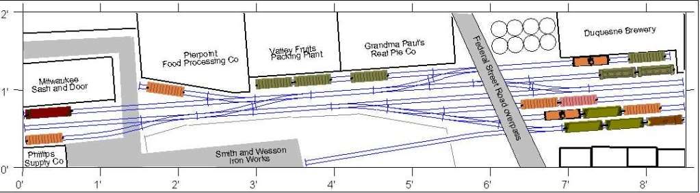
 Here is an example of a small H0 scale 8 1/2 foot long switching layout which can be switched, since 7 of the spurs can be switched from the center out towards the corners, while the last two ("Valley Fruits/Grandma Paul's Real Pie Co" and "Smith & Wesson Iron Works") are switchbacks where the length of the tails have been carefully calibrated (tail for "Smith and Wesson" is long enough for engine and two cars, while the tail of the other switchback up top is long enough for an engine and one car without first pulling car from the Dubuque Brewery siding in the upper right hand corner to create more work space)


 Here is a 17 foot H0 scale plan for a prototype location:

 Could be done in 9 foot length in N scale. Or a little less - axing stuff on the left - making the siding/runaround smaller. Based on a prototype location near Silver Spring Drive in Milwaukee.

 Anyways - a model railroad switching layout has to be switchable. So you need to select a location that supports that when you pick what to model, and you need to adapt the plan to make it switchable.

 Some more background information on the subjects of modelling prototypes and selective compression, from articles on Byron Henderson's web site:

"Perils of the Prototype":  http://mrsvc.blogspot.com/2006/11/tricky-traps-5-8.html
"Caricature, copy or Close enough":  http://mrsvc.blogspot.com/2009/06/caricature-copy-or-close-enough.html
"Compresive Selection":  http://mrsvc.blogspot.com/2009/04/selective-obsession.html


 Smile,
 Stein


Reply 0
BDF

A couple hours after I posted

A couple hours after I posted my previous I came to the same general conclusion; that is that this locale in Flag or even Flag itself isn’t a very interesting subject for a switching layout. I will say a couple things about the Flag idea. I’m limited to 80” in width so that’s why I had to reverse the switch into the right most industry. If I was building a conventional layout I would have stuck with the prototypical S curve on that spur (plus there’s another customer on that spur). You’ll notice too that the lumber yard is actually reversed in its orientation; I was trying too hard to fit those four customers in. 
 
I’ve ditched the idea of sticking with a prototypical switcher because I don’t have the room to model a subject that I’m interested in (i.e. something on the Seligman sub) so I whipped up a “protolance” switcher based on the Kingman airport industrial district late last night. I think it’s quite a bit better but probably still needs work. There are also some peculiarities with some of the track spacing between sidings, mostly associated with my newness to 3rd planit. For instance the sidings with the crossover on the bottom right are all screwed up but I should be able to make it work with no problems in terms of fitting in that location. 
 
 
At first I wasn’t going to keep it until I noticed there is a customer that does actually have a crossover on their siding and it may provide an escape for the RS. The siding/runaround is 33” which is pretty good, that’s about 7-9 cars. The half loop at the far left end is representative of the wye that comes off the main into the district. I might set it up for a small detachable staging cassette. I think it’s a better stab at it. It’s still a subject I’m interested in modeling, has enough prototypical aspects to satisfy that craving yet still has enough opportunity to enable an interesting ops plan.
 
Brad
Reply 0
steinjr

N scale switching layout critique

 Mmm - looking at the maps and aerial pics and bird's eye view of Flagstaff more closely, some modelgenic scenes seems to be:

 - Purina (?) plant at E Nestle Ave ( http://www.bing.com/maps/default.aspx?v=2&FORM=LMLTCP&cp=pw300y5q1xc9&style=b&lvl=1&tilt=-90&dir=0&alt=-1000&phx=0&phy=0&phscl=1&scene=36141920&encType=1). Switching would be exclusively in-plant switching, but it might have proved interesting to do that, if that sounds interesting to you.

 - You have the area you picked - west of N Enterprise Road. If I was going to model anything here, I would have focused on the rightmost spur in your plan, which when you look closely using "bird's eye view" seems to serve three industries with a total of four spurs, configured like this: 

  /></p><p> </p><p>Continuing westwards, you have the area I mentioned, bounded by South Agassiz Street and South Lumber street. Here you have an interesting track configuration, which however would be hard to model:</p><p><img rel=  If you go down along that industry spur, you have an interesting industry at the end of that spur - with a number of tanks :  http://www.bing.com/maps/default.aspx?v=2&FORM=LMLTCP&cp=pvyvg85px0g7&style=b&lvl=2&tilt=-90&dir=0&alt=-1000&phx=0&phy=0&phscl=1&scene=36153852&encType=1

 Continuing west, there is an interesting mini scene by South Beaver Street - a team track like ramp for side and end unloading of cars on one side of the mainlines, and a building that looks like a railroad station on the other side: http://www.bing.com/maps/default.aspx?v=2&FORM=LMLTCP&cp=pvzfcv5pw64n&style=b&lvl=2&tilt=-90&dir=0&alt=-1000&phx=0&phy=0&phscl=1&scene=36149136&encType=1

But I think you would have to do a bit of cut and paste to create a composite scene consisting of parts from here and there to create an interesting switching layout from Flagstaf.

 Your Kingman Airport Industrial District layout looks promising, though.

 Smile,
 Stein


Reply 0
Reply